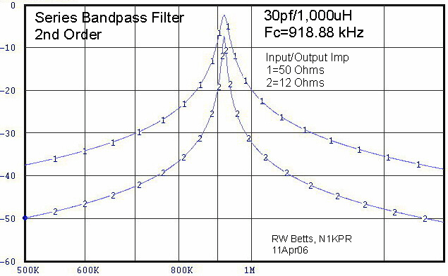
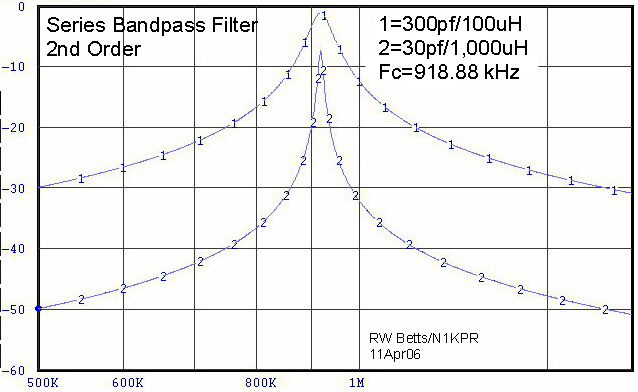
Here is a BP filter centered in the AM broadcast band with a 10:1 ratio-shift of the L and C components.
Note that when the C is high relative to the L value, the loss is minimal, but the filter Q is broadbanded.
Conversely, when the L is high relative to the C component, the Q is increased, but the loss is greater.
Coil loss will vary with the R component of the choke coil. The coils used here have a Q factor of 200 and the source and terminal loads are 12 Ohms. When the Q remains the same, as the ratios are changed, the result will be a proportional change in the R component. Additionally, when examining filter circuit analysis results, other factors must be considered. Band pass or band stop filters should not be designed solely on the basic resonance formula. There's why. A true balanced filter has "equal and opposite" reactances and phase shift on either side of the center frequency. This is the complementary condition associated with a symmetrical design - Butterworth-type filter - their characteristics are predictable.. However, when the reactance magnitude and phase shift angles in the C and L components are not equal and opposite, other resultant characteristics appear. This is NOT apparent in the simplified resonance formula which does not take into account such parameters (see curve # 2 below). NOTE: Since preselectors are parametric, each filter stage will be symmetrical at only one specific frequency - and no other, (every time you turn the inductor switch to another band, the capacitor can only select one specific Butterworth condition in that range). To further understand these conditions, I suggest the experimenter model the above conditions, IE; select a specific frequency and configure various L and C combinations to resonate at that frequency. Please note, in your results, the bandwidth (skirt angle or tightness) of the various pass bands of the various combinations - that is the final Q of the filter. This is demonstrated below using ELSIE (find on Google or Yahoo) filter analysis program (free).
Series resonant filters increase Q as impedance goes down.
Parallel resonant filters (tank) increase Q as impedance increases.
Here is a filter from above with a 4:1 impedance ratio change.
It is obvious that the Q is higher in the 12 Ohm loop, but the loss is greater.
In the higher impedance circuit there is less loss and a lower Q factor.
For preselector design, curve 2 is most desirable.