 |
|
|
|
|
|
|
|
|
|
|
|
|
|
|
|
|
|
|
|
|
|
|
|
Filter Networks and Impedance |
|
|
|
Next Back Home |
|
|
|
|
|
Previously, we have seen how an L/C product which is high in L proportion and low in C (L/C Ratio) produces a higher Q filter (tighter bandwidth skirts) and that the converse is true; a ratio that produces the same product but is higher in C than L, is more efficient, but not as tight in bandwidth (Q).
Now we can see the effects of the loop impedance of the circuit in which the filter will be inserted and the relationship to series and parallel resonant circuits. |
|
|
|
 |
|
 |
|
|
|
|
|
|
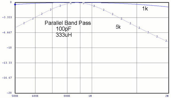
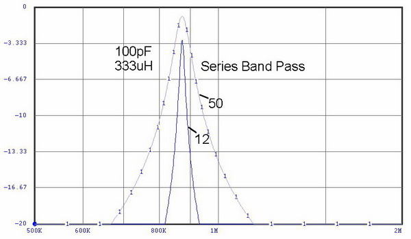
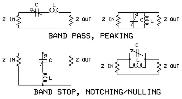
Here are two ways to provide Band Pass filtering. Note the two important design parameters that these graphs illustrate: Impedance and configuration affect performance.
In the series tuned circuit, the filter Q rises as the circuit impedance drops. The opposite is true for the parallel (tank) circuit. Rule: Impedance is minimum in a series-tuned circuit and max in a parallel tuned circuit when at resonance. (curve numbers represent the impedance of the circuit loop - equal input and output impedances) |
|
|
 |
|
|
 |
|
|
|
|
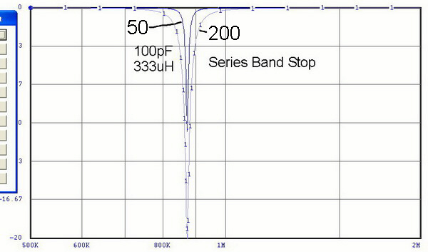
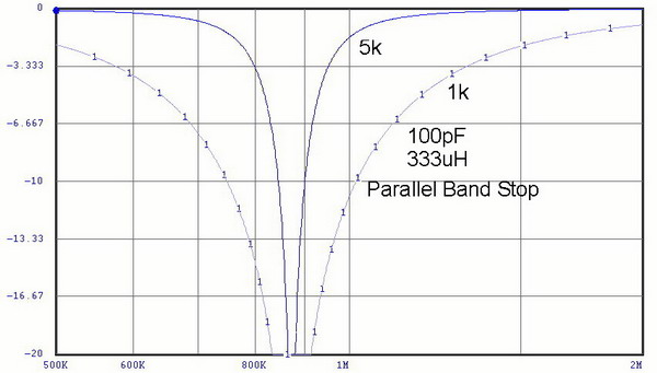
| The same effects can be seen in the Band Stop filters. The difference here is that the series-tuned filter is now used in the "shunt" mode where it is across the signal path. Consequently, working in a higher impedance circuit, its effects are greater. |
|
|
|
 |
|
|
|
The four configurations, for reference. |
|
|
|

|
|
|
|
09 June 06 |
|