There are component parameters in tuned circuits which may be exploited to add benefits to the filter's utility.
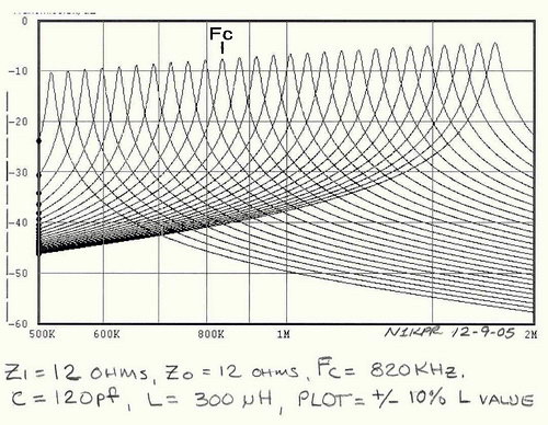
In its parametric function, the above sweeps were performed with a constant value of "C." Utilizing chokes with a "Q" value of 100 (throughout), and shifting their "L" value (+) and (-) 10 %, the skirt bandwidth, for a gived dB value of attenuation remains constant. The effective bandwidth may be increased or decreased (broadened) by a complementary change in the L and C values. For example, the plots above were run with a "mid-band" C value of 120 pF (15-365 air variable capacitor), and the Fc choke is 300uH. If the choke was increased to 600 uH (doubled) and the cap reduced to 60 pF (halved) the Q (bandwidth) of the individual filters would be increased. Conversely, if the choke was reduced to 150 uH and the cap increased to 240 pF the passband Q would be broadened.
Obviously, to the user, this is an advantage: When tuning the preselector for the highest Q (tightest bandpass), the capacitor should be setat a low capacatance value (say, less than 100 pF), and the tapped coil switched for greatest signal level. Then, the cap is tuned to peak the signal. For broad preselection, the opposite procedure would be used: Setting the cap to the high end of its range and tuning the coil as above.
An original preselector design incorporated a "Q spoiler" control, which in effect added the utility of a "bandwidth' control. It was, simply, a series impedance inserted after the input isolation transformer and just before the output transformer. By adjusting the two-gang, 50 Ohm potentiometer from zero Ohms to full resistance, we effectively could swing the Q of the circuit through an impedance ratio of 4:1. Since these preselectors are generally passive devices, the insertion loss would increase from about 1.5 dB to about 6 to 10 dB (1 to 2 S-units), depending where the filters were centered.
To circumvent the losses, subsequent preselectors included a 15 dB preamplifier which could be used to regain the lost signal level. However, this was usually not necessary, since the radio's AGC circuits would automatically adjust for the loss. Of course, under certain DX conditions, the amplifier is a great asset. Another component exploitation, was that when the preamp was switched off, the preamp's gain control could be used as an attenuator for the strong local flamethrower stations.
Air Variable Cap
set to
Inductor 15pF 365pF
33mH 55KHz 230KHz
10mH 90KHz 450KHz
3.3mH 150KHz 800KHz
1mH 280KHz 1.3MHz
330uH 350KHz 2.5MHz
100uH 1MHz 4MHz
33uH 1.5MHz 6MHz
10uH 3MHz 4MHz
3uH 5.5MHz 25MHz
1uH 11MHz 40MHz
