TRICONEX PLC
![]()
The TRICON is a state-of-the-art programmable logic and process controller that provides a high level of system fault tolerance. This section describes fault tolerance and lists the main features offered by the TRICON system.
Fault Tolerance.
Fault tolerance, the most important capability of the TRICON System, is the ability to detect transient and steady-state error conditions and to take appropriate corrective action on-line. With fault tolerance, there is an increase in safety and an increase in the availability of the controller and the process being controlled.
The TRICON provides fault tolerance through Triple,Modular Redundant, (TMR) architecture. The system consists of three identical system legs (except for the Power Modules which are dual redundant). Each system leg independently executes the control program in parallel with the other two legs. Hardware voting mechanisms qualify and verify all digital inputs and outputs from the field; analog inputs are subject to a mid-value selection process. Because each leg is isolated from the others, no single-point failure in any leg can pass to another. If a hardware failure occurs in one leg, the faulty leg is overridden by the other legs. Repairs consist of removing and replacing the failed module in the faulty leg while the TRICON is on-line and without process interruption. The system then reconfigures itself to full TMR operation.
Extensive diagnostics on each leg, module and functional circuit immediately detect and report operational faults by means of indicators or alarms. The diagnostics also store information about faults in system variables. If faults are detected, the operator can use the diagnostic information to modify control actions or direct maintenance procedures.
From the user's point-of-view, setting up applications is simple because the triplicated system operates as one control system. The user terminates sensors and actuators at a single wiring terminal and programs me TRICON with one set of application logic. The TRICON manages the rest.
Features of the TRICON System
To ensure the highest possible system integrity at all times, the TRICON:
- Provides Triple Modular Redundant architecture whereby each of three identical system legs independently executes the control program, and specialized hardware/software mechanisms "vote" all inputs and outputs.
- Withstands harsh industrial environments.
- Enables field installation and repair to be done at the module level while the controller remains on-line. Replacing an I/O module does not disturb field wiring.
- Supports up to 74 I/O modules (analog and digital) and optional communication modules that interface with Modbus masters and slaves, Honeywell Distributed Control Systems (DCS), other TRICONs in Peer-to-Peer networks, and external host applications on 802.3 networks.
- Provides integral support for remote I/O modules located up to two kilometers (1.2 miles) from the Main Chassis.
- Executes control programs written in Relay Ladder Logic and developed and debugged with a separate workstation called TRISTATION.
- Provides intelligence in the input and output modules to reduce the workload of the Main Processors. Each I/O module has three microprocessors. Input module microprocessors filter and de-bounce the inputs and diagnose hardware faults on the module. Output module microprocessors supply information for the voting of output data, check loopback data from the output terminal for final validation of the output state, and diagnose field-wiring problems.
-Provides integral on-line diagnostics with adaptive-repair capabilities.
-Allows normal maintenance while the TRICON is operating, without disturbing the controlled process.
-Supports "hot spare" I/O modules for critical applications where prompt service may not be possible.
SYSTEM CONFIGURATION
Physically, a basic TRICON system consists of modules, the chassis in which modules are housed, field wiring connections and the TRISTATION MSW programming workstation. This section briefly describes these major elements and provides general specifications.
TRICON Modules
TRICON modules are field-replaceable units consisting of an electronic assembly housed in a metal spine. Each module has a protective cover that ensures no components or circuits are exposed even when a module is removed from the chassis. Offset backplane connectors make it impossible to plug a module in upside down, and "keys" on each module prevent the insertion of modules into incorrect slots.
The TRICON supports digital and analog input and output points, as well as thermocouple inputs and multiple communication protocols. These interfaces are handled by selecting modules from the list shown in Table 1-A. Refer to the manuals in the binder called "Manuals for Communication Modules" for more information about die communication protocols and interfaces offered by Triconex.
Table 1 A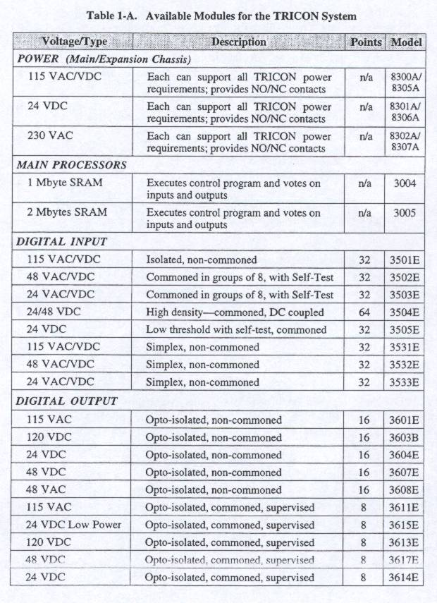

TRICON Chassis
There are three types of TRICON chassis: Main Chassis, Expansion Chassis and Remote Extender Chassis. A TRICON System can include up to fifteen chassis housing any appropriate combination of input, output, and hot spare modules as well as communication modules (see Figure 1.1).
fig1.1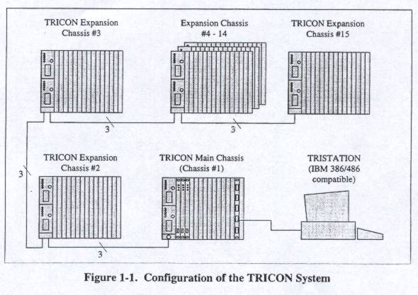
The Main Chassis of the TRICON system houses me Main Processor modules and up to four I/O sets. I/O modules within a chassis connect by means of a triplicated RS-485 bi-directional communication port. Expansion Chassis (chassis 2-15) support up to five I/O sets each. Expansion Chassis connect to me Main Chassis by means of a triplicated RS-485 bi-directional communication port.
The total standard cable length, which can be used to join a set of Main and Expansion chassis, is up to 30 meters (100 feet). Remote Extender Chassis enable a system to extend to remote locations up to two kilometers (1.2 miles) from the Main Chassis.
THEORY OF OPERATION
Triple-Modular Redundant (TMR) architecture (shown in Figure 1.2) ensures fault tolerance and provides error-free, uninterrupted control in the presence of either hard failures of components or transient faults from internal or external sources.
Every I/O module houses the circuitry for three independent legs. Each leg on the input modules reads the process data and passes that information to its respective Main Processor. The three Main Processors communicate with each other using a proprietary high-speed bus system called the TRIBUS.
fig1.2.
Once per scan, the Main Processors synchronize and communicate with their neighbors over the TRIBUS. The TRIE US votes digital input data, compares output data, and sends copies of analog input data to each Main Processor.
The Main Processors execute the control program and send outputs generated by the control program to the output modules. In addition to voting the input data, the TRICON votes the output data. This is done on the output modules as close to the field as possible to detect and compensate for any errors that could occur between the TRIBUS voting and the final output driven to the field.
For each I/O module, the system can support an optional hot-spare module. If present, the hot-spare takes control if a fault is detected on the primary module during operation. The hot-spare position is also used for on-line system repairs.
![]()
![]()
![]()