MODULES
![]()
Main Processor Modules
A TRICON system contains three Main Processor modules. Each controls a separate leg of the system and operates in parallel with the other two Main Processors (see Figure 1.3). A dedicated I/O communication processor on each Main Processor manages the data exchanged between the Main Processor and the I/O modules. A triplicated I/O bus, located on the chassis backplane, extends from chassis to chassis by means of I/O bus cables.
As each input module is polled, the appropriate leg of the I/O bus transmits new input data to the Main Processor. The input data is assembled into a table in the Main Processor and is stored in memory for use in the hardware voting process. The individual input table in each Main Processor is transferred to its neighboring Main Processors over the TRIBUS. During this transfer, hardware voting takes place. The TRIBUS uses a direct memory access programmable device to synchronize, transmit, vote and compare data among the three Main Processors.
If a disagreement occurs, the signal value found in two out of three tables prevails, and the third table is corrected accordingly. One-time differences which result from sample timing variations are distinguished from a pattern of differing data. Each Main Processor maintains data about necessary corrections in local memory. Any disparity is flagged and used at the end of the scan by the TRICON's built-in fault analyzer routines to determine whether a fault exists on a particular module.
The Main Processors put corrected data into the control program. The 32-bit main microprocessor and a math coprocessor execute the control program in parallel with the neighboring Main Processor modules. The control program generates a table of output values which are based on the table of input values according to customer-defined rules built into the application. The I/O communication processor on each Main Processor manages the transmission of output data to the output modules by means of the I/O bus.
fig1.3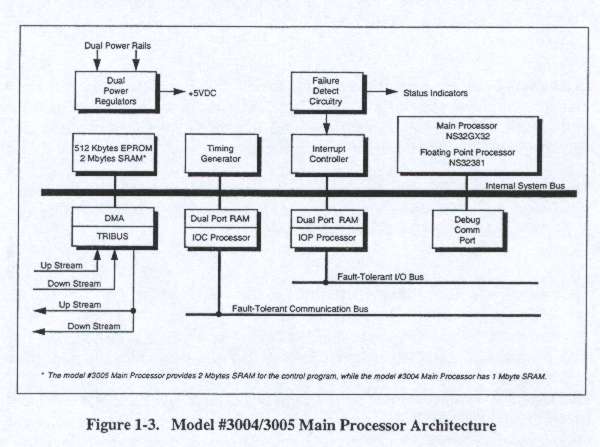
Using the table of output values, the I/O communication processor generates smaller tables, each corresponding to an individual output module in the system. Each small table is transmitted to the appropriate leg of the corresponding output module over the I/O bus. For example. Main Processor A transmits the appropriate table to Leg A of each output module over I/O Bus A. The transmittal of output data has priority over the routine scanning of all I/O modules.
The I/O communication processor manages the data exchanged between the Main Processors and the communication modules using the communication bus which supports a broadcast mechanism. The TRICON provides a total of 2 Megabytes SRAM and 512 KBytes EPROM (operating-system memory) with model #3005 Main Processors. (Model #3004 Main Processors provide 1 Megabyte SRAM and the same amount of EPROM.) Approximately 80% of the SRAM is available for the user-written control program and SOE data, while the remaining SRAM is used by the operating system for I/O data, diagnostics and communication buffers. In the event of an external power failure, the SRAM is protected by batteries built into the Power Modules of the Main Chassis. In the absence of power to the TRICON, the batteries maintain the integrity of the program and the retentive variables for a minimum of six months.
The Main Processor modules receive power from the dual Power Modulesand power rails in the Main Chassis. A failure on one Power Module or power rail does not affect system performance.
MAIN PROCESSORS — Models #3004 & #3005
A TRICON chassis houses three Main Processor (MP) modules, each serving one leg of the controller. The Main Processors are adjacent to the Power Modules in the TRICON chassis. Each processor independently communicates with its I/O subsystem and executes the user-written control program. The three MPs compare data and the control program at regular intervals.
The model #3004 Main Processor offers 1 Mbyte of SRAM, while the model #3005 Main Processor offers 2 Mbytes of SRAM. This is the only difference between the two Main Processor models available for Version 8 TRICON systems.
The rest of this section provides the following information about the Main
Processors:
- compatible communication modules
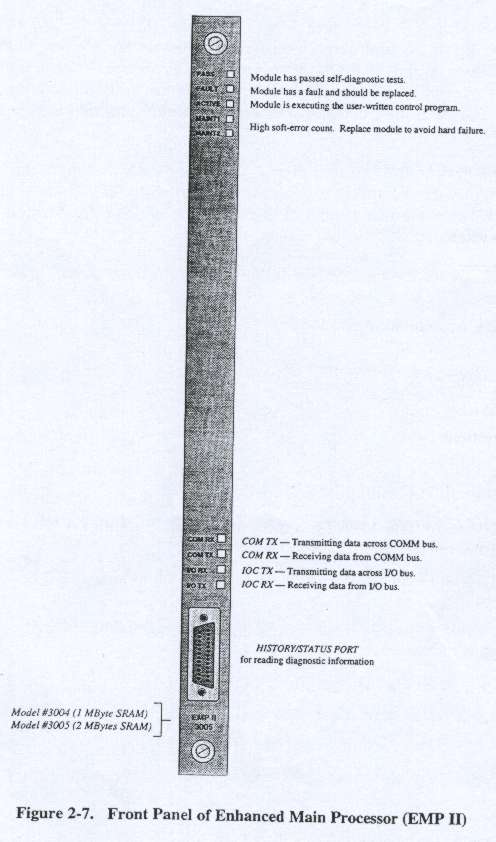
- physical description
- SOE capability
- diagnostics
- specifications
Compatible Communication Modules
Model #3004 and #3005 Main Processors are compatible with the following
communication modules:
- Model #4108 Enhanced Intelligent Communication Module (EICM),
Non-Isolated
- Model #4118 Enhanced Intelligent Communication Module (EICM),
Isolated
- Model #4400 Safety Manager Module (SMM)i
- Model #4508 Hiway Interface Module (HIM)
- Model #4318 Data Communication Module (DCM)
- Model #4328 Network Communication Module (NCM)
( Availability depends on Honeywell support for Release 500 of the TDC-3000 DCS.
Bus Systems & Power Distribution
As shown in Figure 1-4, three triplicated bus systems are etched on the chassis backplane: the TRIBUS, the I/O bus, and the communication bus. The TRIBUS consists of three independent serial links operating at 4 Mbaud. It synchronizes the Main Processors at the beginning of a scan. Then each Main Processor sends its data to its upstream and downstream neighbors. The TRIBUS takes the following actions:
- Transfers analog, diagnostic and communication data
- Transfers and votes digital input data
- Compares data and flags disagreements for the previous scan's output data and control program memory
An important feature of TRICON architecture is me use of a single transmitter to send data to both the upstream and downstream Main Processors. This ensures the same data is received by the upstream processor and downstream processor.
If you are planning large applications that use the TRICON's Sequence of Events (SOE) capability, you should select the model #3005 Main Processors with the extra SRAM.
fig1.4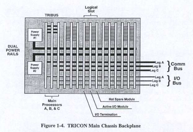
Each I/O module transfers signals to or from the field through its associated field termination module. Three positions in the chassis tie together as one logical slot. The first position holds the Field Termination Module; the other two positions hold the active and hot-spare I/O modules. The termination module is tied to both I/O module positions of the logical slot by connections at the top of the backplane. Each connection extends from the termination module to both primary and hot-spare I/O modules. Therefore, both the active module and the hot-spare module receive the same information from the field termination module.
The 375 Kbaud triplicated I/O bus transfers data between the I/O modules and the Main Processors. The I/O bus is carried along the bottom of the backplane. Each leg of the I/O bus runs between one Main Processor and the corresponding legs on the I/O module. The I/O bus extends between chassis using a set of three I/O bus cables.
The 500 Kbaud communication bus runs between the Main Processors and the communication modules.
Power for the chassis is distributed across two independent power rails and down the center of the backplane. Each module in the chassis draws power from both power rails through dual power regulators. There are four sets of power regulators on each input and output board: one set for each leg (A, B, and C) and one set for the status indicators.
Digital Input Modules
Each digital input module houses the circuitry for three identical legs (A, B and C). Although the legs reside on the same module, they are completely isolated from each other and operate independently. Each leg conditions signals independently and provides optical isolation between the field and the TRICON (the 64-point High-Density Digital Input Module is an exception — it has no isolation). A fault on one leg cannot pass to another. In addition, each leg contains an 8-bit microprocessor called the input/output processor which handles communication with its corresponding Main Processor.
Each of the three input legs asynchronously measures the input signals from each point on the input termination module, determines their respective states, and places the values into input tables A, B and C respectively. Each input table is regularly interrogated over the I/O bus by me I/O communication microprocessor located on the corresponding Main Processor module. For example. Main Processor A interrogates Input Table A over I/O Bus A. DC models of the digital input modules can self-test to detect "stuck ON" conditions. This is an important feature for safety systems since these are usually set up with a "de-energize to trip" capability. Therefore, it is important to know that the system can detect an OFF state in the input. To test for "stuck ON" inputs, a switch within the input circuitry is closed to allow a zero input to be read by the optical isolation circuitry. The last data reading is frozen in the I/O processor while the test is running.
Digital Output Modules
There are three basic types of digital output modules:
- Supervised digital output modules
- DC voltage digital output modules
- AC voltage digital output modules
Every digital output module houses circuitry for three identical, isolated legs. Each leg includes an I/O micro-processor which receives its output table from the I/O communication processor on its corresponding Main Processor. Special "quad" output circuitry votes the individual output signals just before they are applied to the load. This voter circuitry is based on parallel-series paths which pass power if the drivers for A and B, or B and C, or A and C command them to close.
Each type of digital output module executes a particular Output Voter Diagnostic (OVD) for every point. In general, during OVD execution the commanded state of each point is momentarily reversed on one of the quad output drivers, one after another. Loop-back on the module allows each microprocessor to read the output value for the point to determine whether a latent fault exists within the output circuit. (For devices that cannot tolerate a signal transition of any length, OVD on both AC and DC voltage digital output modules can be disabled.)
A supervised digital output module provides both voltage and current loopback, allowing complete fault coverage for both energized-to-trip and de- energized-to-trip conditions. In addition, a supervised digital output module verifies the presence of the field load by doing continuous circuit-continuity checks. Any loss of field load is annunciated by the module. A DC voltage digital output module is specifically designed to control devices which hold points in one state for long periods of time. The OVD strategy for a DC voltage digital output module ensures full fault coverage even if the commanded state of the points never changes. On this type of module, the output signal transition normally occurs during OVD execution, but is guaranteed to be less than 2.0 milliseconds (500 microseconds is typical) and is transparent to most field devices.
On an AC voltage digital output module, a faulty switch identified by the OVD process will cause the output signal to transition to the opposite state for a maximum of half an AC cycle. This transition may not be transparent to all field devices. Once a fault is detected, the module discontinues further iterations of OVD. Each point on an AC voltage digital output module requires periodic cycling to both the ON and OFF states to ensure 100 percent fault coverage.
Analog Input Modules
On an analog input module, each of the three legs asynchronously measures the input signals and places the results into a table of values. Each of the three input tables is passed to its associated Main Processor module using the corresponding I/O bus. The input table in each Main Processor module is transferred to its neighbors across the TRIBUS. The middle value is selected by each Main Processor, and the input table in each Main Processor is corrected accordingly. In TMR mode, the mid-value data is used by the control program; in duplex mode, the average is used.
Each analog input module is automatically calibrated using multiple reference voltages read through the multiplexer. These voltages determine the gain and bias required to adjust readings of the analog-to-digital converter. Analog input modules and termination modules are available to support a wide variety of analog inputs, in both isolated and non-isolated versions: 0-5 VDC, 0-10 VDC, 4-20 mA, thermocouples (types K, J, T and E), and resistive thermal devices (RTDs).
Analog Output Modules
The analog output module receives three tables of output values, one for each leg from the corresponding Main Processor. Each leg has its own digital-to- analog converter (DAC). One of the three legs is selected to drive the analog outputs. The output is continuously checked for correctness by "loop-back" inputs on each point which are read by all three microprocessors. If a fault occurs in the driving leg, that leg is declared faulty, and a new leg is selected to drive the field device. The designation of "driving leg" is rotated among the legs so that all three legs are tested.
Termination Modules
A field termination module is an electrically passive circuit board to which field wiring is easily attached. A termination module merely passes input signals from the field to an input module or passes signals generated by an output module directly to field wiring, thereby permitting removal or replacement of the input or output module without disturbing field wiring. There are two classes of passive field terminations available for the I/O modules:
- Internal terminations for high-density applications
- External terminations for remote marshaling of field wiring
Communication Modules
By means of the communication modules described in this section, the TRICON can interface with Modbus masters and slaves, Honeywell Distributed Control Systems (DCS), other TRICONs in Peer-to-Peer networks, and external hosts running applications over 802.3 networks. The Main Processors broadcast data to the communication modules across the communication bus. Data is typically refreshed every scan; it is never more than two scan-times old.
Enhanced Intelligent Communication Module fEICM)— Supports RS-232 and RS-422 serial communication with external devices at speeds up to 19.2 Kbaud. This EICM provides four serial ports which can interface with Modbus masters, slaves, or both; or TRISTATION. The module also provides a Centronics-compatible parallel port.
Hiway Interface Module CHIM) — Acts as an interface between a TRICON controller and HoneywelFs TDC Data Hiway, enabling higher-order devices on the Hiway, such as computers and operator workstations, to communicate with the TRJCON. The HIM allows redundant BNC connection directly to the Data Hiway, and has the same functional capacity as up to four extended Data Hiway Port (DHP) addresses. The use of a hot spare module for on-line replacement is fully supported by the HIM.
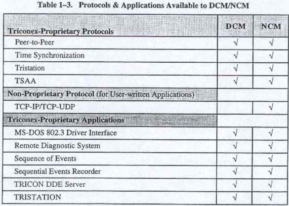
Safety Manager Module (SMM) — Used solely for communication with Honeywell's TDC-3000 Universal Control Network (UCN), one of three principal networks of the TDC-3000 Distributed Control System. The SMM allows the UCN to specify the TRICON as a "safety node" which communicates process information at full network data rates for use anywhere on the TDC-3000. The SMM transmits all TRICON aliased data and diagnostic information to TDC-3000 operator workstations in display formats that are familiar to the Honeywell operators. Data Communication Module (DCM) & Network Communication Module (NCM) — These modules support 802.3 networking over a high-speed 10 Megabit/second data link, using the protocols and applications listed in the following table:
table 1.3
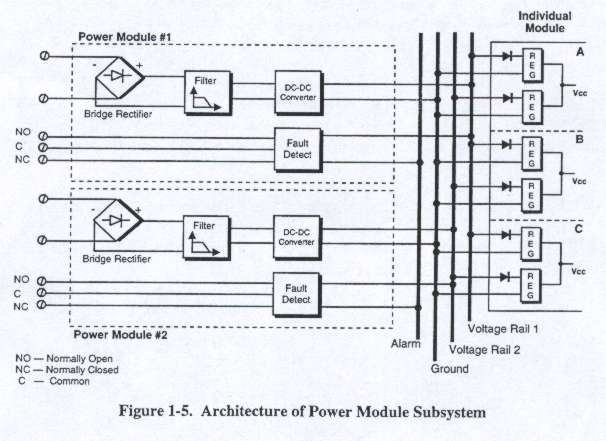
Power Modules
Each TRICON chassis houses two Power Modules arranged in a dual-redundant configuration. Each module derives power from the backplane and has independent power regulators for each leg. Each can support the power requirements for all the modules in the chassis in which it resides, and each feeds a separate power rail on the chassis backplane, have built-in diagnostic circuitry which checks for out-of-range voltages and over-temperature conditions. A short on a leg disables the power regulator rather than affecting the power bus (see Figure5).
![]()
![]()