Boiler’s Operation Philosophy
![]()
The
primary function of the boiler is to produce the steam in sufficient quantities
to meet the needs of the plant. In
order to do this, the boiler requires fuel, air and water at all the times
during operation. The heat released
during the combustion of the fuel produces steam from the water. In most cases, the steam is heated further before leaving the
boiler. This process is continuous for the entire period that the boiler is in
operation.
The amount of steam varying according to the load changes. In order to change the steam output, the boiler must change the rate of the air and fuel combustion and rate of water flow proportionately. In order to respond to these changes accurately and efficiently, various control systems are used on the boiler.
Steam
Boiler
Main
Parts:
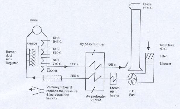
FD
Fan :
It sucks the air from the atmosphere and give for combustion chamber.
Air Fuel
Ratio is 1Kg of Gas needs 10kg of air & 2.5kg of the access air.
Steam
Heater:
Steam heater will be used only during oil firing to increase the inlet
air temperature to the boiler.
Air
Pre-Heater:
It uses to make a heat exchange between hot flue gas going out and inlet
cold combustion air to the boiler.
Burners:
The burner is the device that permits controlled burning of fuel inside
the furnace. The burner mixes the
fuel with the required amount of air and directs the flame into the combustion
area. Each boiler has six burners.
The burner comprises of gas burner and oil burner with atomizing steam
connection.
Burner
consists of:
·
Air
Register:
used to give an enough quantity of air to the burner for good combustion.
·
Ignition
Gun: used
to give ignition spark to the burner for firing.
·
Flame
Detector:
used to monitor the flame.
Cooling
Air Fans:
There are two cooling air fans are used to cool the burners and
surrounding equipment’s like flame detector, oil firing gun, gas burners.
Gas
Supply Line:
Fuel gas comes from fuel gas reducing station, which maintains constant
fuel gas pressure. In case of failure or low header pressure line 2 takes over
and keeps the header pressure to the required pressure.
Fuel
Oil Supply Line:
Fuel oil comes from fuel oil tank, through F.O transfer pumps it comes to
oil system. Fuel oil is maintained
at 5-bar pressure by PLC control and F.O is supplied to fuel oil supply pumps
which boosts to 22 bar pressure.
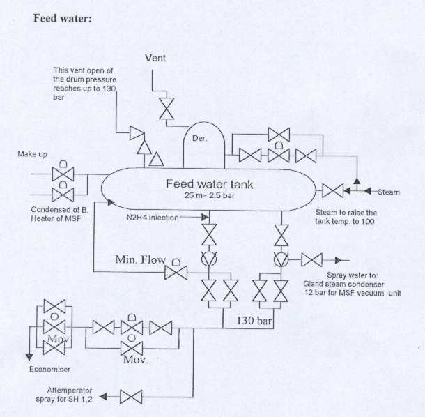
De-aerator:
It used to remove the oxygen and any other gases which contents in the
water. Deaerator is used to store
the water, which is feed pump inlet for each boiler.
Feed
Water System:
Treat the water by removing dissolved solids and dissolved gases.
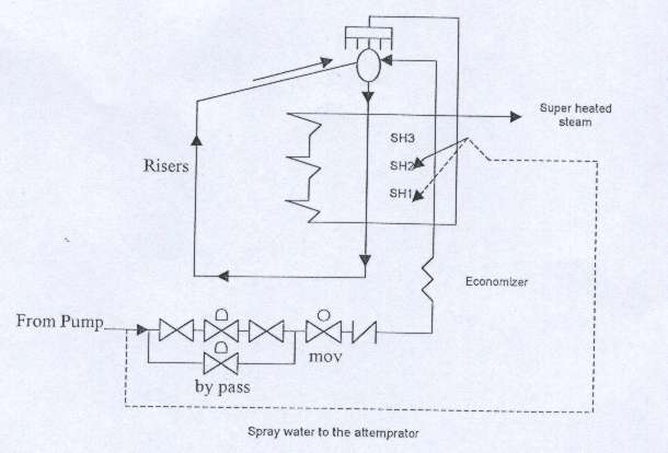
Steam
Drum:
The primary purpose of the steam drum is to separate the steam from the
boiler water.
Super
Heater:
They are used to increase the steam temperature before it leaves the
boiler.
Economizer:
The economizer is used to heat the boiler feed water before it enters the
steam drum.
Soot
blowers:
The unburned carbon is called the soot. In order to remove the soot and ash deposits during operation, soot blowers are installed in the various locations in the furnace.
Waste Heat Recovery Boiler (WHRB):
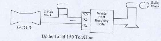
The
function of the waste heat recovery boiler is typical to the normal boiler 1 and
2, but there are some differences in operation modes, burners and fuel.
Operation modes:
-
Exhaust
mode: this mode is used in normal operation by using flue gas, which is
coming from Gas Turbine Generator ( as well as supplementary firing by burners.
In this case the bypass stack damper and combustion air FD fan are closed
and boiler inlet damper (BID) is opened.
-
Island
mode: this mode is typical to independent operation mode because burners
only operate the boiler. The boiler
is separated from flue gas from GTG by close boiler inlet damper (BID) and open
bypass stack damper and combustion air FD fan.
Burner group:
There
are seven burners are grouped in three groups as the following:
1.
Group I: burner elements 3 and 5.
2.
Group II: burner elements 1, 4 and 7.
3.
Group III: burner elements 2 and 6.
Each
burner is consist of:
1.
Pilot burner.
2.
Flame detector.
3.
Cooling air.
4.
Spark.
Sealing air fan:
The function of sealing air fan is to seal and protect FD fan from
heating up by flue gas in exhaust operation mode.
Also it seal bypass damper from flue gas leakage to the stake at exhaust
mode. The WHRB protection system
will trip the boiler when the seal air pressure less than 20 mBar.
BURNER MANAGEMENT SYSTEM (BMS):
The
B.M.S. is the system, which decides and takes appropriate action according to
the safety and protection of the boiler. Example: Fuel
Gas pressure coming Low or Low /Low according to set point, Boiler will trip by
the protection logic through BMS when there is low/low alarm.
Receives
three different inputs for each of the measured variable.
Any one differs from the other two readings, PLC generates a discrepancy
alarm and as soon as second measured variable differs from the set point defined
in the PLC, a trip alarm is generated and the boiler shuts down for safety and
protection of the equipment. This
is called two out of three voting system.
INTERLOCK
SYSTEM:
Interlocks
are devices that sense off-limit operating conditions related to the start-up or
shutdown of the boiler. These
devices act to permit a sequence of control actions when starting or shutting
down the boiler. In this
application, they are called permissive interlocks.
Other interlocks cause a shutdown sequence of control actions.
In this application, they are called tripping interlocks.
All permissive to start and tripping signals will mention in the
protection system title of this report.
PROTECTION
SYSTEM:
To
prevent or to save the plant from any damage, we use Protection Logic to perform
the following:
·
Warn the boiler operator of hazardous operating conditions.
·
Protect the equipment from damage.
·
Ensure that the equipment functions in the proper manner.
·
Shut the equipment down when unsafe conditions occur or when operating
limits are exceeded.
Boiler
Protection & Sequence
Boiler Start Up
·
Start burner 1
·
Release start up burner 1
·
Sequence burner 1 sequence fail reset
·
Boiler purged
·
Protection stop
·
Burner 1 oil presale
·
Burner 1 gas presale
·
Condition to step 02
·
Condition to step 03
·
Condition to step 04
·
Condition to step 05
·
Fuel gas. Quick shutoff valve step 07
·
Condition to step 08
·
Condition to step 09
·
Ignitor on
·
Burner 1 oil on
·
Burner 1 gas on
·
Condition to step 13
·
Sequence burner 1 on (End Feedback)
·
Release start up burner 1
·
Set air flow to ignition start position from burner 1
·
Reset Ignition set point from burner 1
Boiler Protection Active
·
Fuel gas vent valve close
·
Fuel gas quick shutoff valve close
·
Gas burner 1 select
·
Atomizing steam open
·
Fuel oil quick shutoff valve close
·
Fuel oil quick shutoff valve close oil burner 1 select
·
Oil scavenge valve opened
·
Air slide UV291A open
·
Flame monitor off
·
Ignitor not on
·
Start up sequence fail
·
Stop sequence fail
·
Gas burner select
·
Sequence burner guide gas protection active
·
Oil burner select
·
Sequence burner guide oil protection active
·
Burner 1 sequence reset
·
Burner 1 start sequence running
·
Burner 1 stop sequence running
·
Burner 1 on
Shut
Down Inputs:
·
Boiler drum level low
·
Furnace pressure high
·
Control air pressure low
·
Flue gas damper not open
·
Damper before air heater not open
·
Emergency Push button (console)
·
Emergency Push Button (DCS)
·
Emergency Push Button ( Ground Level)
·
Emergency Push Button (Boiler Top)
·
Emergency Push Button (9m Level)
·
24VDC to Solenoid Operate Valve failure
·
Cooling air pressure low
·
Fuel gas pressure high
·
Fuel gas pressure low
·
Fuel oil pressure low
·
Fuel oil temperature low
·
Atomizing steam pressure low
·
Scavenger steam pressure low
·
Combustion air flow low
·
Low fuel gas flow
·
Low fuel oil supply flow
·
FD Fan on
·
Combustion air is excess of the set point
Boiler
Start Permissive Signal
1.
At lease one oil/gas burner on.
2.
Fuel oil / gas control valve closed.
3.
Remote selected.
4.
Fuel gas selected.
5.
Boiler purged.
6.
Burner start/ stop sequence not running.
BOILER
CONTROL SYSTEM
The
basic objective of the boiler control system during normal operation is to
maintain constant steam pressure at the steam header going to the plant.
In other words the primary control command originates with the steam
pressure in the lines downstream from the secondary superheater.
All other control signals will follow from the measurement and desired
response to the steam pressure. At
the same time all control loops are designed for safe operation and will shut
the systems down in the event of operating problems.
The boiler control system must perform the following functions:
·
Provide feed water to the boiler.
·
Maintain steam output pressure.
·
Provide combustion air to the furnace.
·
Provide fuel to the burners.
·
Provide draft to the furnace, flue and stack.
·
Provide blow down of the drums.
The flow of feed water entering the boiler must equal the flow of steam
and blow down water leaving the boiler. Also
the feed water control system must maintain the feed water, the steam flow rates
and the steam drum level at the same time, which was called three-element
control system.
The
burner management system (BMS) and Programmable Logic Control (TRICONEX PLC)
controlled the boiler control system.
DRUM LEVEL CONTROL SYSTEM:
The
steam flow transmitter that is compensated for pressure, temperature and the
feed water flow transmitter, gives signals to the steam and water flow computing
relay. The two signals are balanced
each other in the computing relay. Any
change in the flow rates will be transmitted to steam flow, water flow and drum
level computing relay. The level
transmitter, compensated for pressure and temperature, at the steam drum also
sends a signal to this relay. At
this point, the signal from the level transmitter is balanced with the signal
from the signal from the steam flow/water flow relay. Any difference between the two signals is transmitted through
the manual/automatic selector switch to the feed water control valve.
This signal positions the valve to provide the rate of feed water flow
equal to the steam flow rate, while maintaining the steam drum level at the same
time.
Blow
down control normally uses the conductivity of the boiler water to establish the
blow down flow rate.
AIR AND FUEL COMBUSTION CONTROL SYSTEM:
On
the fireside of the boiler the primary control functions are to:
·
Control combustion airflow to the burners
·
Control fuel flow to the burners
·
Control furnace draft and flue gas flow
These functions are also closely related and must be kept in proper
balance to maintain the correct firing rate and combustion gas flow to the
furnace which controls the steam pressure at the steam header.
The airflow must be kept in proportion to the steam flow. This is because, there is a direct relationship between the energy input (fuel and air) and the energy output (steam). By keeping the steam flow/air flow ratio at the proper value, maximum combustion efficiency can be maintained.
![]()
![]()