![]()
The
function of a burner management system (BMS) is to assure safe operation of the
combustion associated with boilers, ovens, kilns, process heaters and furnaces.
The BMS provides a safe start-up procedure and stops fuel flow if conditions are
detected that affect the safety of the unit.
With
the advancement of microprocessor technology, programmable systems have become
the preferred solution for burner management design. When issues like
documentation, configuration management, diagnostics, capabilities for operator
graphics and communications to other Plantwide control systems are considered,
the advantages of programmable technology over relay/solid-state technology
become very significant. Since the failure modes of microprocessor technology is
not readily predictable, the Australian Gas Association (AGA) and a number of
other international standards and regulatory agencies (NFPA, TUV, FM, IRI) have
established recommended practices and guidelines for applying this technology in
burner management applications.
There
are strong economic reasons to ensure combustion equipment operates safely.
These reasons include possible equipment losses, personnel injury and
loss' and production downtime as a result of an accident.
When risk analysis is combined with life cycle costing techniques, many
companies realise that the financial impact of safety risk is higher than
imagined.
Gas
& Fuel Authorities are bringing out newer, tougher requirements including
requirements for approvals from independent testing agencies like TUV.
The IEC61508 standard for the functional safety of
electrical/electronic/programmable electronic (E/E/PE) safety-related systems
has been released and the Australian version AS61508 will be fully published
soon. Safe operating combustion
equipment design is not becoming easier.
The
latest Australian Standard AS3814/AG 501 – 2000 for industrial and commercial
gas-fired appliances states that for a Programmable Electronic System (PES) to
gain acceptance on Type B appliances the following applies as in clause 2.26.3,
sections: -
“If it is desired to use a PES controller to perform safety-related
functions, then it shall be a redundant safety-related PES and possess a TUV
safety certificate to the appropriate safety class of DIN V 19250 or some
equivalent certificate. Only TUV approved "firmware" (or equivalent)
is to be used in the controller.”
“Like computer programs, the only true way of assessing a PES
user-program to ensure that it functions the way it was designed, is to test run
the program. It is not possible to
inspect a PES program in its entirety by visual examination and conclude that
the program does what it is required to do under all possible operating
situations.
Therefore
in order to ensure the integrity of the PES user software, the person/company
who designed the system shall have QA accreditation, and shall have adhered to
the principles outlined in AS 61508. It is the designer's responsibility for the
development of the program, and for test-running the program by simulating the
inputs, and proving that the outputs occur at the right time and duration. A
signed written statement to that effect shall be submitted to the Authority.”
The
NFPA 8502 standard for the prevention of furnace explosions/implosions in
multiple burner boilers, 1999 edition clause 4-3.2.1, lists the following
minimum failures that must be evaluated and addressed: -
(a)
Interruptions, excursions, dips, recoveries, transients, and partial
losses of power
(b)
Memory corruption and losses
(c)
Information transfer corruption and losses
(d)
Inputs and outputs (fail-on, fail-off)
(e)
Signals that are unreadable or not being read
(f)
Failure to address errors
(g)
Processor faults
(h)
Relay coil failure
(i)
Relay contact failure (fail-on, fail-off)
(j)
Timer failure
“The
system shall conform at a specified Safety Integrity Level (SIL) to IEC 61508,
Part 1, General requirements. The hardware architecture shall include
self-checking firmware, external and internal watchdog systems, redundant
processors, and dual I/O cards as required to achieve the specified SIL.
Software architecture shall include communications drivers, fault handling,
executive software, input/output functions, and derived functions as required to
achieve the specified SIL. Redundant components shall be separated so as to
reduce common cause failures.”
This
need to meet regulations and properly implement safety protection equipment adds
another dimension to the trade offs that must be made by design engineers.
The BMS maintains safe operation of the boiler during start-up, operation, and shutdown. Both PLCs and DCSs can accommodate safety and process control in a single processor, but the National Fire Protection Association, Factory Mutual Research Corporation, and good engineering practice call for independence between burner management systems and all other control systems.
Early automated BMS were either proprietary hardware or relay based. Since the 1980s, PLCs are preferred for their reliability, flexibility, configurability, and lower life cycle cost.
With any automated electronic control-based system, the designer must pay close attention to failure modes. Safety features that can be designed into a BMS include input checking, critical output monitoring, external watchdog circuit, coil monitoring, fuse monitoring, circuit breaker monitoring, and related alarming and diagnostics.
Many other processes in a power house can be controlled with PLCs to cut installed system cost, reduce spare parts requirements, speed maintenance and operator training, and ease installation and troubleshooting.
Safety
PLCs incorporate output monitoring into their I/0 module hardware using special
circuitry and an onboard microprocessor to generate the diagnostics, as
illustrated in Figure 2. This eliminates the wiring and programming required by
general purpose PLCs. Furthermore,
this relieves the application controller from the burden of generating these
diagnostics.
Output
monitoring provides valuable diagnostic information.
However, it can do nothing more than annunciate the problem on its own.
In order to convert the potentially dangerous failure into a safe failure, an
additional technique must be applied in addition to the output monitoring.
Most safety PLCs incorporate protected or guarded outputs. Figure 4 shows the incorporation of a diagnostic cut-off relay to the typical safety PLC block diagram, which provides guarded outputs. Note that the relay is also monitored for proper function. Here, the diagnostic generated by the faulted output or relay must be manually cleared before the relay can be re-energised.
 fig.4
fig.4
Safety PLCs also employ watchdog timers, however, watchdog timers are integral to the modules and usually implemented redundantly. That is, every CPU circuit is monitored by two watchdog timers, and the timers also monitor each other to detect watchdog timer failure. If either watchdog trips, the diagnostic cut-off relay is de-energised. Figure 6 depicts the addition of watchdog timers to the typical safety PLC block the diagram. As shown, the watchdog timer has direct control of the relay, de-energising it upon a watchdog time-out.
 fig.6
fig.6
Power
Monitoring
Figure 8 shows the complete safety PLC output module block diagram with the addition of the power monitor circuit. Like the trip alarm, the power monitor circuit detects if the power supply goes over or under range and can automatically trip the diagnostic cut-off relay to protect the outputs. This circuit can also detect if the main fuse is blown.
Communication Protection
Address Verification
To
insure input data is originating from the correct module and going to the
correct module, the processor should incorporate some form of address
verification. Safety PLCs use
redundant serial data links to communicate between the processor and the I/0
modules. Serial communications
allow for source and destination addressing to be embedded into messages and
compared with the hardware address established by the backplane.
Parallel backplane designs typically found in general purpose PLCs do not
usually incorporate any address verification.
All
programmable control system memory (RAM, ROM, and EEPROM) should be fully tested
upon power-up and continuously tested on-line with background diagnostics'
Volatile memory (RAM) should be battery backed and a low battery diagnostic
should indicate to the operator when a battery needs to be replaced.
A
"common cause" failure is defined as the failure of two or more
similar components due to a single stress event (a single cause).
The key word here is "stress." Stressor events include
electrical events like power spikes, lightning, and high current levels.
Mechanical stress includes shock and vibration.
Chemical stress includes corrosive atmospheres, salt air, and humidity.
Physical stress includes temperature.
Heavy usage including high data rates is even a stress, especially to
system software. If the stress
level is high enough, two or more similar components can fail at the same time.
Software
may be the most significant contributor of all to the common cause failure rate.
A "stress' to a software system is the combination of inputs,
timing, and stored data seen by the CPU. Imagine
a fault tolerant system with two or three processors where all the CPUs are
running the exact same program in lock-step synchronous operation.
The CPUs will all see the
exact same inputs, the same stored data with the same timing.
The chance of simultaneous failure due to a common software bug is high.
A
Safety PLC can achieve “common cause strength” through a number of
mechanisms:
·
Physical
separation of redundant units. The
worst implementation has redundant circuits on the same circuit board.
The best implementation allows redundant circuits to be located in
different cabinets.
·
Asynchronous
operation of redundant units to reduce software common cause.
The
worst implementation has identical software running the same functionality in
perfect synchronisation. The best
implementation runs asynchronously with different operating modes between
redundant units.
·
Diversity.
The
worst implementation has identical software and hardware in redundant units.
The best implementation uses diverse components that respond differently
to a common stress.
·
High
strength hardware and software. Other
important parameters include the overall ruggedness of the safety PLC and the
use of a systematic audited software development process.
Typically
a specially designed safety PLC, provides high reliability and high safety via
special electronics, special software and pre-engineered redundancy.
The safety PLC has I/0 circuits that are designed to be fail-safe with
built-in diagnostics. The CPU of a
safety PLC has built-in diagnostics for memory, CPU operation, watchdog timer
and all communications systems. I/0
module addressing is done via serial communications messages that have full
automatic error checking. Figure 9
shows the architecture of a non-redundant safety PLC.
The 1oo1D (one out of one with diagnostics) architecture uses the special
diagnostic circuits to convert dangerous failures into safe failures by de-energising
the output. This is the most cost effective safety PLC solution and meets IEC
61508 SIL 2 requirements.
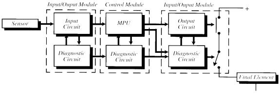
Figure 9.
The 1oo1D architecture uses special diagnostic circuits to convert
dangerous failures into safe circuits.
 Figure 10.
The 2oo3 architecture is designed to provide safety and
Figure 10.
The 2oo3 architecture is designed to provide safety and
Conceptually,
each of the two units reads inputs, calculates, and stores outputs. The
diagnostic circuits monitor proper operation and will de-energise a second
series output switch if a failure is detected.
Any potentially dangerous failure is converted into a safe failure if
detected by the diagnostics. If the
diagnostics work perfectly, the system is fail safe.
High availability is achieved through the parallel combination of the two
sets of electronics. If one side fails safely, the other side maintains the load
and the protection function.
The loo2D architecture requires good self-diagnostics. Diagnostic techniques have improved considerably; however, it is arguable that perfect self-diagnostics can be achieved. Therefore, in order to assure high safety integrity, actual implementations of the loo2D provide interprocessor communication between the logic solvers. A comparison of input data and calculation results between the two units provides complete protection in addition to the self-diagnostics. When the comparison of either unit detects a mismatch, the system is de-energised (fail-safe).
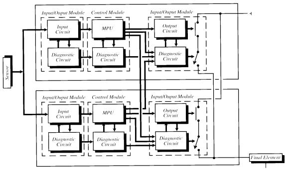 Figure
11. The
1oo2D architecture provides safety, via diagnostic circuits
Figure
11. The
1oo2D architecture provides safety, via diagnostic circuits
and extra series output switches, availability and common
CONCLUSION
There
are many aspects of a Burner Management System that contribute to its operating
safety and meeting IEC 61508 and regulatory agency requirements.
For example and not covered by this paper, much can be done with flame
detectors, field sensors and actuators, such as voting redundant sensors, using
analog transmitters in place of switch interlocks, and installing limits
switches on valves. There are also
now more certified field sensors becoming available that are designed to meet
the standards. However, the device that controls all of the system I/O plays a
major role in the operating safety of the system.
Selection of the control system is just as, if not more critical, than
the selection of the associated field hardware.
![]()
![]()