Rebuilding Houdaille Shocks
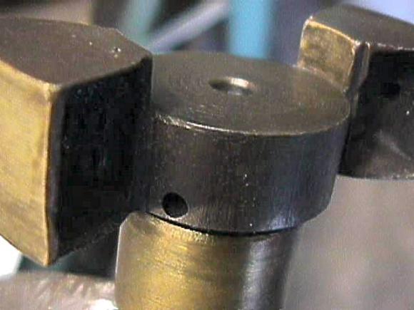
I say this, yet people have rebuilt these shocks in the past. The photograph below is evidence of that.
As far as I can determine, modern rebuilders limit machining operations to installing a bushing in the inner cover. No attempts are made to refurbish the rotor impeller, stator and shock body, although some rebuilders may substitute parts cannibalized from other shocks. Cost of the service ranges from $60 to $125, which is not unreasonable, considering that the shocks must also be disassembled, cleaned, tested and repainted.
Bushing replacement should centralize the rotor, but does nothing to address wear on the pump elements. Perhaps 10% of the shocks floating around swap meets can be restored to service in this manner. The remainder are too far gone to develop a pressure head.
It is feasible, barely feasible, to recondition every wearing surface on almost any Houdaille. Whether it is economically practical, is another question. George Sprotte computes the cost of a shock built in this way at between $500 and $600. The emotional cost may be even higher, considering the refractory material, the side-tracks to build fixtures and special tooling, and the steep learning curve. Try this and Houdailles will haunt your dreams.
There are various approaches to the problem. In my case, I resolved to contain the madness by making no large investments in tooling or outside services. Metal spray and exotic plastic coatings were out. I would use what I had, which consisted of a 115v MIG welder, a South Bend lathe dating from FDR’s second term, a 6-inch rotary table and a vertically challenged Chinese mill.
Basically the project amounted to recapitulating the Houdaille manufacturing process on a minuscule scale and with lightweight tooling. If A.B. Shultz and his Houde company built 20,000 shocks an hour, I hoped to build one a week. Four working shocks came out of the effort.
General
- Make things easy on yourself by selecting good cores, worn just beyond the useable limit. Unscrew the inner cover and try to move the rotor from side to side. Play should be limited to about 1/16 inch. Reject cores that are severely rusted or warped.
- Time spent building fixtures will not be wasted. At the very minimum, you will need a
 three- and four-jaw chuck adapter for the rotary table so you can switch operations between the lathe and mill without losing the setup.
- Initially I assumed that dimensions could be standardized as they are for rebuilt alternators or starters. This was not possible. Design variations and the mysterious "wandering center" make each shock unique. And thinking about it, it’s presumptuous for a rebuilder to suppose he could achieve parts interchangeablility when the original manufacturer did not make that claim.
- Leave as much material in place as possible -- even at the expense of an occasional rust pit or other surface imperfection. Not only does aggressive metal removal increase the work load, at some point, one must become concerned for shock body integrity. A Houdaille is, after all, a pressure vessel
- Fairly loose shocks can develop decent levels of pressure with 50/50 mixture of STP and hydraulic oil. We aim for a sliding fit between adjacent surfaces with the inner cover torqued hard down.
Mounting Flange
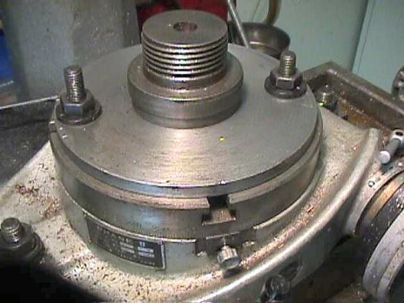
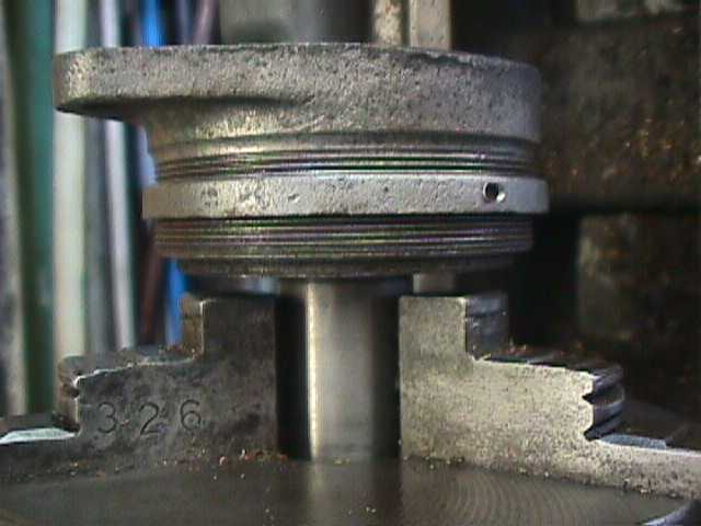
The first step is to true the rough-cast mounting flange to establish a datum in that plane for subsequent machine work on the shock body and inner cover. A flat mounting surface should also eliminate distortion when the shock is bolted to the car frame and assist in heat transfer.
One’s initial impulse might be to hold the shock body by the OD threads in a three-jaw chuck. Unfortunately, the threads are not even approximately normal to the mounting base, and must have been cut on a different setup than used at other stages in the manufacturing process.
After giving the problem some thought, I decided to make a fixture that would mount flush against the shoulder formed by the reduced diameter of the working chamber wall. The inner cover seats against this shoulder, which sees no wear or corrosion.
The fixture consists of a 2 7/8" disc cut from 1/2” steel plate and welded to a heavy bar. 20 TPI threads, undercut at the outboard end, match those on the shock body ID. A facing cut across the disk assures that the fixture seats flat against the shoulder.
A light skim cut should be enough to true the mounting flange. Do not attempt to clean up deep corrosion pits or locally shallow areas.
Bushing Installation
All Houdailles, even dummy units fitted to show cars, benefit from a proper shaft bushing.
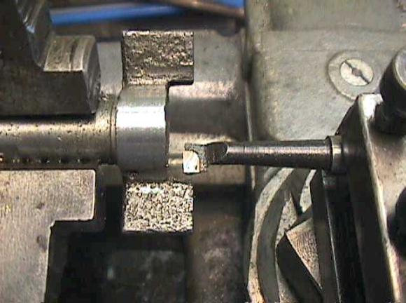
Rotor Shaft (Wing Shaft) Reconditioning- Fill any corrosion pits on the shaft. A small MIG welder using .023” mild steel wire and C-25 shielding gas works well enough, but a DC stick machine would probably do a better job.
- Chase the upper set of needle valve threads with a 1/2” x 20 TPI bottoming tap. Cut matching threads on a 1/2-inch-diameter aluminum rod about 2” long and install in the end of the rotor shaft. This rod will function as a false center.
-
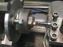
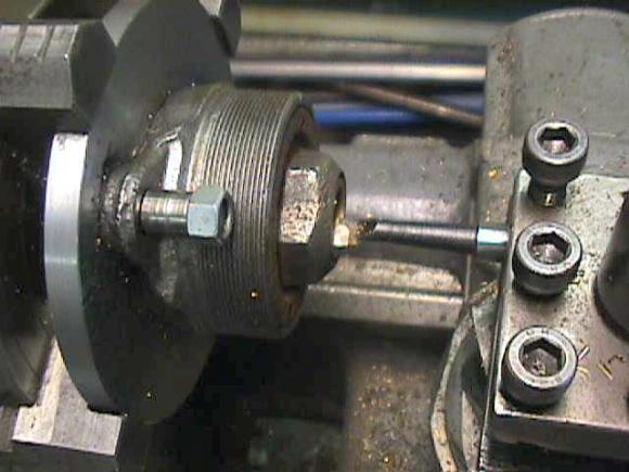
Mount the rotor by the impeller end in a four-jaw lathe chuck and center to TIR +/- .001.” Centering is easier and more secure, if you make a
 holding fixture. The rotor shaft will be worn out-of-round, which means that the flats the factory milled (however inaccurately) on the end of the shaft represent the best available dial-indicator register.
- Carefully drill a center hole in the end of the aluminum rod that you previously threaded into the needle-valve boss. The centering hole will not be concentric with the rod OD since the needle-valve boss is never drilled on a true center. But the should be centered with the shaft flats. Recheck TIR.

If you have access to a tool post grinder, use it. Otherwise, take very light cuts with a sharp high-speed steel tool. Remove as little metal as necessary to restore concentricity. George Sprotte points out that the as-new shaft diameter ranges between .9250 - .9255 inch. Standard cylinder-type reservoir seals work for shaft diameters as small as .9000 inch; undersized seals are available for .8750-inch shafts. Maintain the original radius at the shaft/rotor interface.
Bushing InstallationI don’t know how Houdaille centered the bushing bore over the working chambers, or how precisely it was centered. Bushing bores are neither concentric with inner-cover OD’s nor with internal shock-body threads.
-
Mount the shock body in a four-jaw lathe chuck. A round
 fixture takes some of the hassle out of centering and is less likely to creep out of register during machining.
- Center the shock body with a dial indicator. For want of a better surface, I place a dial indicator (fitted with a mushroom tip) on the internal threads. The thread circle is guaranteed to be warped, and readings must be averaged to attain something approximating a TIR of +/-.001 inch.
- Install and torque down the inner cover. When the cover can be tightened no further, the bleed plugs should be in the correct position and reference marks, made prior to disassembly, should align.
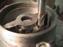
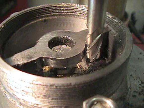
- Bore the bushing boss to 1.000” to accommodate a slightly oversized 1-inch OD x 3/4-inch ID x 3/4 inch brass bushing, available from MSC and other tool houses.
- Remove the inner cover from the shock body. Lightly oil the parts and, using a vise, press in a new bushing from the outboard end of the inner cover. Cut a chamfer on the lower end of the bushing to provide clearance for the shaft/wing radius.
-
Finish
 the bushing to size on a lathe, with the inner cover torqued down to the centered shock body. Bushing/rotor shaft clearance should be .0015 -.0020 inch.
- Drill the 1/8-inch bleed port through one side of the bushing.
- Cut a 1/-inch wide fluid collection groove to a depth of 0.015 inch in the bushing ID and in line with the bleed port.
- Trim the excess length from the upper end of the bushing and chamfer the bushing to accommodate the shaft seal.
Inner Cover Refacing
Inner covers almost always exhibit some degree of corrosion and wear on the inboard face that forms the roof of the working chambers. But simply skimming the inner cover on a lathe will not do. There are complications:
-
The resurfaced cover should torque down to its original position, with the bleed plugs up and flanking the stator. The 20 TPI pitch of the inner threads means that you can remove metal in .050-inch increments without upsetting the initial orientation.
Note: as pointed out below in "Rotor Impeller and Stator" shock-body or inner-cover threads may have to be sacrificed for the inner cover to make up against the shoulder. - Unfortunately, the pitting on many inner covers requires more than a single .050-inch cut to remove. Go deeper and you will cut away the retaining pin secures the replenishing-valve ball to the cover casting.
But, not to worry. George Sprotte developed a technique, detailed below, to adapt a grease fitting in place of the replenishing valve.
Resurfacing the inner cover in one of the final operations, done after work has been completed on the shock body.
- Torque down the inner cover on the shock body (previously centered in a four-jaw chuck) and make a light cut on the raised rim at outboard face of the cover. This helps insure that the subsequent cut on the inboard face is square with the original or refaced shock-body shoulder.
- Mount the internal cover, inboard surface out, by the hex in a three-jaw chuck. Back the cover into the chuck so that the previously squared surface registers against the chuck jaws.
- Face off the inner surface of the cover. One revolution of cover threads = .050 inch. Some bronze welding may be required to fill deep pits.
- Test fit the inner cover to the shock body, torquing it down snugly. Small, clockwise adjustments to bleed-plug orientation can be made with a belt sander. Serious misalignment is best dealt with by plugging and redrilling the bleed plug holes.
Note:The fit of the inner cover will change if shoulder height is reduced to compensate for material removed from the shock floor and/or rotor faces. - In most instances, you will come out ahead by replacing the replenishing valve with a straight 1/8-inch pipe thread Zerk fitting. (I have not had much luck with standard 1/4-inch thread plugs.) Cut away the crimp at the bottom of the fitting threads, and extract the coil spring and ball. Turn a brass plug slightly larger than the fitting ID and centerdrill the port. Discard the spring, and assemble the fitting with the ball and plug. Drill and thread the inner cover in the original replenishing-valve position or, at any rate, near the bottom of the reservoir. Start the tap straight with a drill press. Fitting threads should be wrapped with Teflon tape.
Shock Body ID and Floor
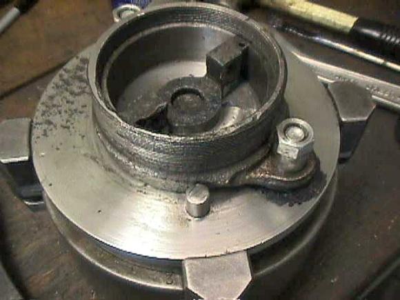
Remove the stator as described under "Houdaille Disassembly."
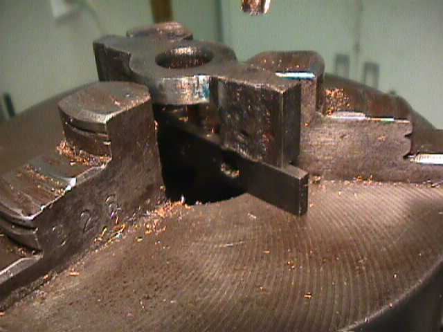
Mount the shock body in a four-jaw chuck, preferably with the aid of a fixture. Register on the internal threads and aim for a TIR of +/-.001 inch. Readings should be averaged to compensate for the inevitable distortion of the thread circle.
The shock body cavity can be milled, although I prefer to use a lathe. A cemented carbide boring bar, applied with moderate cutting force, works for the ID. The floor responds best to sharp, single-pointed HSS tools mounted in right and lefthand holders.
As mentioned before, material removed from the shock body floor must be compensated for by lowering the shoulder, or ledge, which forms the seat for the inner cover. The ability of the inner-cover threads to hold oil pressure limits the amount of material that can be removed. Hogging out the ID may lead to sealing problems and can impact the stator stator mounting arrangement. Less is more, as far as shock bodies are concerned.
Rotor Impeller and Stator
The cleanest, most workmanlike solution to the many difficulties presented by the rotor would be to fabricate a new one from steel billet. Short of that, one must turn down the shaft to accept a new rotor bushing (described above) and render the impeller serviceable. All working surfaces -- upper and lower sides of the wings, wing tips, shaft end, hub OD and hub ID -- should be concentric with the body axis, parallel to the floor and positioned within .001 inch of adjacent parts.
Rotor rework involves use of two lathe chucks, transferred back and forth between the lathe and rotary table. The rotor is held in a three-jaw chuck; the shock body centered in a four-jaw. If the rotor is removed from the chuck for test fitting, its orientation relative to one of the numbered jaws is noted to reduce the effects of chuck runout.
Which parts to overlay with weld and which to machine undersized? My experience suggests that welding should be limited to the impeller wing tips, impeller hub ID (the tooth-like protuberances under the impeller), and the inboard ends of the stator wings. The hub OD and the disk-like pad upon which the rotor rides are milled undersize.
- Mount the rotor in a three-jaw chuck and make a clean-up cut on the hub ID. Wing tips can be prepared for welding with a tool post grinder or belt sander.
- Apply a weld overlay. In the opinion of welding specialists consulted, a DC stick machine and any of several high-tech filler rods would give the best results. I tried the lowest-carbon mild steel MIG wire obtainable (good penetration and coverage, but hard) and gas brazing (difficult to apply, heat warped and annealed the impeller), before hitting upon silicon-bronze wire and C-25 shielding gas. Bronze gives good penetration and fair coverage on bright surfaces. Although quite tough, the bead can be machined with sharp tools. As a bonus, a bronze-lined shock will probably outwear every other friction surface on the car.
- Mount the rotor in a three-jaw chuck and turn down the built-up rotor tips to within .001 inch of the refinished shock-body ID. Trial fit in the shock body and verify that the rotor turns through its full arc without binding. Don’t forget to orient the pinch-bolt notch.
- Without removing the rotor from the chuck, transfer the chuck to a rotary table centered under the mill. Using a 3/8-inch HSS cutter, mill enough material from the hub OD to restore concentricity. Measure hub diameter.
-
Move the chucked-up rotor back to the lathe and machine the weld overlay previously applied to the
 impeller hub ID. Measure this diameter.
- Place a piece of abrasive paper on a machine work table and polish the underside of the stator to remove any high spots.
- Install the stator in the shock body cavity and mill OD of the disc-shaped pad upon which the stator wings mount.
 We need to establish a .001-inch clearance with the impeller hub ID. Pad thickness will be adjusted later.
Note: Houde machined stator pads off-center, as can be demonstrated by using the shock body as a stator-holding fixture. The eccentricity may have assured correct rotor assembly. We save a little time by machining the pads on center.
- Clean up the inboard ends of the stationary wings and apply a weld overlay.
- Using the body cavity as a fixture, mill the overlay applied in the previous step to size. Test fit the rotor over the stator.
- Verify that the stator seats flush against the shock-body floor. Stator ends may require notching to compensate for the reduction in floor height.
- Make a vertical cut on top of the stator disc to restore surface finish.
-
Measure the installed thickness of the stator disc. Repeat this measurement on the lower end of the impeller to determine the clearance between the undersides of the rotor wings and body floor.
Installed Pad Thickness - Rotor Undercut = Distance Rotor Stands Off From Floor
- Mount the rotor in the lathe and square off the lower surface of the wings, removing metal until the rotor stands off .001 inch from the shock body floor.
- Square off the upper surface of the rotor wings.
- Place the rotor in the shock body and measure the distance from the shoulder to the upper surface of the wings. This distance, less .001 inch for running clearance, represents the amount to be removed from the ledge and stator top. I have found it easier to cut the ledge in a lathe and use a mill on the stator.
- Once shoulder/stator height is correct, torque down the inner cover to verify that it makes up hard against the shoulder. You can use bearing blue to establish the pattern of contact. It may be necessary to compromise sealing by undercutting the inner-cover threads. A better approach (currently under test) might be to install a spacer between the cover and shoulder.
- Because of the reduction in stator height, it will be necessary to redrill and groove one or both stationary wings for the top-side check valve(s). At present, we convert shocks with side-mounted check valves to 50/50 operation.
Needle Valve
It’s a good idea to replace the needle valve and, in any event, to lap the valve tip against the seat with valve-grinding compound. A leaking needle valve invalidates any sort of test of shock action.
As of yet, we have not found it necessary to chase the lower set of needle valve threads, which appear to require a special 3/8” x 20 TPI tap.
Reservoir Cup
Some cups require light machining to restore the seal at the underside of the rotor-shaft hole. Elongated shaft holes can trued by boring, but the diameter of readily available o-rings or cylindrical-type seals limits the amount of material that can be removed.
Conclusion
Well, that’s it. Assembly procedures are trivial by comparison. Seal the ends of the stator with epoxy (Houde packed the joint with lead), and top off the working chambers with a 50/50 mix of STP and hydraulic jack oil before installing the inner cover. We use Teflon tape on all threaded connections.
Cycle the rotor a few times before screwing on the reservoir cup to check for leaks at the inner cover, bleed plugs and replenishing valve. Install the reservoir cup, mount the shock vertically in the fixture, fill the reservoir to the level determined by the filler plug orientation, and test. We do not have quantitative data at this time: but a functional shock will bind almost solid with the needle valve seated.In honesty, attempting to replicate the Houd approach, using the technology available to them, but with lighter and less precise tooling, has not been satisfactory. A better approach might be to redesign the shock internals.