Houdaille Disassembly
Thanks to the hydroscopic working fluid, the fine threads and decades of exposure to the elements, most Houdailles require radical, heat-intensive methods of disassembly.
This is unfortunate, both because of its effect upon the metal and because of the real hazards involved.
To minimize risk, we have developed the following guidelines. They are offered without a guarantee: in other words, you can do exactly as we say and still get hurt.
- If possible, remove the reservoir cover (sometimes called the outer cover or reservoir cup) before proceeding.
- If you cannot undo the cover, by all means remove the filler plug. Drill out the plug if you have to.
- Loosen the rotor so that it turns a few degrees on its bearing. This should improve the odds that the working chambers vent.
- Wear eye protection and protective clothing.
- Do not heat an assembled shock with a torch. Instead, place the shock in a brazier, barbeque pit, a charcoal-filled hole in the ground, etc., and retreat to a safe distance.
We "cook" the partially disassembled shock in a charcoal fire for three or four hours to burn out the seals and glycerin. Then, following the example of Houston-area shock builder Brian Perkins, we drop the shock into a pail of cold water. Within seconds, a loud “burp” signals that water has gotten inside the unit. The shock is retrieved and, while still too hot to touch, disassembled.
Heating shocks releases noxious fumes. Work in a well ventilated area.
Holding Fixture
You should take the time to fabricate a 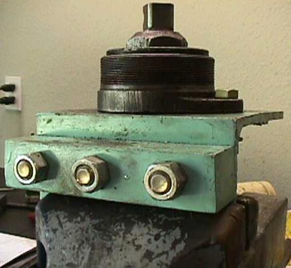 holding fixture. The fixture, based on a design by George Sprotte, should be mounted with the shock vertical, so that disassembly forces pass down through the vise to the floor. Mounting it horizontally can result in a broken vise. We know.
Reservoir Cover (Outer Cover)
Unscrew the reservoir cover by turning it counter-clockwise with a strap wrench. Apply penetrating oil and lightly tap the part in the vicinity of the threads as it is unscrewed. The lock ring is drilled for a spanner-wrench, although a chain wrench works as well.
Inner Cover (Bushing Nut)
If you look closely, you will see a dimple cast into the inner cover between the two bleed valve plugs. File a notch on the shock body threads adjacent to the dimple as an assembly guide. Upon further disassembly, you will see that the dimple is centered over the stator, with the bleed plugs above adjacent working chambers.
Some inner covers may have four or even six bleed plugs. One theory is that the covers were cannibalized in the field and redrilled to fit. It is also possible that tolerance mismatches forced Houde inspectors to redrill some covers.
The standard inner cover incorporates hex for wrench purchase. You will need a 1 9/16” socket, possibly relieved by grinding to clear the square end of the rotor shaft, a 3/4”- drive wrench and cheater bar combination. We usually get by with a five-foot-long cheater, although there is no rule against using a longer one.
If the rotor is frozen, coax it free by turning it a few degrees in either direction with a large Crescent wrench. Otherwise the rotor may break when the inner cover is unscrewed.Now the grunt part: with the shock mounted vertically in the fixture, try to undo the inner cover. Have a helper heat the area adjacent to the threads with a propane torch as you apply torque. In extreme cases, it will be necessary to repeat the “cook and quench” process.
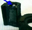
Once the cover is off, support the inner cover on a soft wood block and punch the two bleed plugs down and out. Try not to damage the staking that anchors the plugs against chamber pressure. Note the shallow groove in each plug that extends from the lower (tapered) end to the top. Plugs install with the grooves adjacent to the near edge of the inner cover. By some miracle of French engineering, these grooves vent air and gas-off without loss of fluid.
The replenishing valve, which transfers fluid from the reservoir to the working chambers, is integral with the cover. Careful examination should reveal the small drilled port on top of the cover, about 180° from the bleed plugs. A retaining pin, the end of which is visible on the threaded edge of the cover, holds the 5/32 inch check ball in place.
The underside of the inner cover directly above the stator should be unworn and relatively free of pitting. A comparison between this area and the surface swept by the rotor gives an idea of the amount of wear.
Rotor (Wing Shaft)
Lift out the rotor and note any damage or other anomalies. Most exhibit pronounced wear at the wing tips and hub/stator interface. Exposure to water results in local pitting and may etch a deep groove at the reservoir seal. Many rotors are solid steel, probably forged by Houde. Hollowed-out, skeletal wings appear to be castings that may have been sourced from outside suppliers.
Shock Body
Shock bodies vary somewhat by model year and supplier. A cursory inspection will reveal if corrosion and/or wear on the ID and floor require machine work to correct.
Differential-Action Check Valves. At least three styles of internal check valves are encountered:
- The most common check valve consists of
 Some late production Houdailles incorporate check valves in the rotor.
- Contract-built units sometimes employ a cartridge-type check valves mounted horizontally in the stator wings.
Stator (Stationary Wing)
The stator should remain undisturbed, unless the shock body needs machine work or cartridge-type check valves are to be replaced. Most rebuilders let these sleeping dogs lie, since few vehicle owners can detect the slight ride improvement afforded by working check valves.
Usual Houde practice was to mount the stator to the shock body with pins. Some contract-built units used tongue-and-groove joints, spot-brazed for security. In all cases, the joint formed by the ends of the stator and the shock-body cavity was made pressure-tight by packing it with lead after assembly.
Either of two methods can be used to extract the stator:
- Drill a 1/8-inch hole in the back of the shock body under each pin. Using a small punch, drive the pins up and out. Holes must be filled with weld prior to returning the unit to service.
- Pull the stator with a pair of 8-inch Vise-Grips with a slide hammer extension welded to the end of the adjustment screw. This method works reasonably well if you soak the area with penetrating oil for a few days prior to disassembly.
The stator footprint gives an excellent indication of wear on the shock-body floor.
Cleaning
Bead-blasting may be the fastest, more labor efficient way to proceed. Lacking that equipment, we generally sandblast the heavy rust from the outside of the body casting and soak the body cavity and other parts in muraitic acid for several hours.