![]()
Practical
MIDI packs generating / transmitting
by
Jordan D. Petkov
![]()
Practical
MIDI packs generating / transmitting
by
Jordan D. Petkov
There are two possible
ways to use self-made MIDI controllers, no matter what technology are they based
on. The first
one is connecting to PC souncard wich has embedded MIDI synthesizer. The second
is to use standard MIDI stuff at the other end. Both ways are different when
it comes to requirements to generated signals, more specially to their electrical
characteristics. Timing characteristics are strictly defined by MIDI standard.
In order to be connected to PC soundcard MIDI controller (keyboard etc.) should
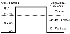
generate TTL compatible signals on its output. Here are TTL levels definitions:

NOTE:
The TTL levels are defined only in 0..+5V window. If you are usind non-TTL levels
(for example: CMOS at 9V), yîu should convert output levels to TTL specified.
Else you could damage your PC soundcard! The undefined zone between 0- and 1-levels
may vary for different TTL types and different items.
Usually PC MIDI interface is combined
with joystick controller and both interfaces are placed at the computer's back
as an 25 pins connector. Here is description of typical MIDI/Joystick connector:
| Picture | Pin | Description |
 |
1
|
+5v |
|
2
|
X button for joystick A | |
|
3
|
X potentiometer for joystick A | |
|
4
|
Ground | |
|
5
|
Ground | |
|
6
|
Y potentiometer for joystick A | |
|
7
|
Y button for joystick A | |
|
8
|
+5v | |
|
9
|
+5v | |
|
10
|
X button for joystick B | |
|
11
|
X potentiometer for joystick B | |
|
12
|
MIDI out | |
|
13
|
Y potentiometer for joystick B | |
|
14
|
Y button for joystick B | |
|
15
|
MIDI In |
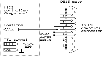
Every MIDI controller generating MIDI packs at TTL levels (like my MIDI keyboard controller) can be connected to PC MIDI interface this way:

NOTE: For such connection you could use 2(3) wires cable. The power supply from PC joystick port is optional. Use it only if you are sure that your device will draw current less than 10-20 miliamperes. It's good idea to use shielded cable (shield is GND connected).
When it comes to connecting self-made MIDI-controller to standard MIDI device (synth etc.), the signals requirements are different from above mentioned. Here comes so called "current circuit loop". What this means?
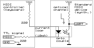
In order to assure that there will be no electrical connection between different MIDI devices on stage, an optical connection is used instead electrical one. The optical connection is done by opto-couples, embedded in standard MIDI devices. This is an standard requirement imposed by MIDI standard. (see Bob McQueer's article). Such devices usually consist of LED (Light Emitting Diode) and photo-transistor placed in common pack:

Some of opto-couples have additional protective diode parallel/reverse connected to LED. It is good practice to add external protective diode the way it is shown on next figure.
NOTE: The MIDI controller and the MIDI device should have their OWN power supply(Vcc) and ground (GND) lines and there is NO electrical connection between controller Vcc and device Vcc as well as between controller GND and device GND! The only one connection is the current loop sourced by controller and driving LED. In fact connection is done by optical channel embedded in opto-couple.
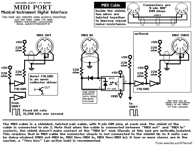
The right part (transistor) is connected to input circuits of the receiver (standard MIDI device UART). The current thru LED should come from transmitter (self-made MIDI controller) in such way that when transmitter transmits logical '0', the LED is on, and when '1' is transmitted, the LED is off. From the other side of this opthical connection photo-transistor goes in conductive state (on) when the LED is on, and back in non-conductive state (blocked) when LED is off. This way its emitter voltage is high (logical 1) when LED is off, and low (logical 0) when on. The standard circuit for coupling MIDI controller and MIDI device is like this one:

NOTE:The
picture represented here is from Jalkanen Album
by Timo Jalkanen. You may also obtain the last version of the album on Timo's
site.
The left part of schematic shows the stuff needed to be included at the controller's side (i.e. keyboard). The right part shows what is (has to be) included in standard MIDI device (synthesizer for example). Note that this is the MIDI standard statement. I couldn't guarantee that every MIDI controller have this module included.
Obviously there should be some requirements
to MIDI controller output signal, since it has to drive a LED. The most common
requirement to drive such LED's are to be capable to source current of 10 miliamperes.
When using +5v supply (most common case) this means to connect LED between power
and ground using serially connected resistors at approximately 500 Ohm (summary).
Usually two identical resistors are used connected to both LED ends. Their value
can be 200 - 250 Ohm. I myself use 2x220 Ohm.
These opto-couples are considered to be best for using in MIDI devices:
PC-900 and 6N138.
You are not indebted to use additional TTL buffers like shown on the picture
if your controller is capable to source current needed for LED driving. In this
case you could connect your device directly to MIDI out connector (ofcource
using two 220 Ohm resistors).
While discussing the pack construction, we will take into these considerations:
The best way to show how the MIDI pack is constructed is to show step by step constructing that comes into PIC processor working in MIDI keyboard controller. I shall use different colours to represent different bit groups.
Suppose that a key C has been pressed on our MIDI keyboard. The MIDI controller has recognized the keynumber and translated it into MIDI note number (60). Now it should generate MIDI command NoteOn for note 60 (C) at velocity 64 and transmit it to MIDI synth on MIDI channel #0 (most used MIDI channel in PC soundcards). The NoteOn command consists of three bytes: the first is Status byte holding event code and channel number, the second is Data byte, holding Note number, the third is Data byte, holding Velocity value. Since a bit can contain only 0 or 1, we have to represent all digits into binary format. Thus we talk about note number '0111100' (7-bit value) and velocity value '1000000' (7-bit value). (By the way, you can use the standard Windows Calculator for such conversions.)
First, we shall construct the Status
byte.
As I said, the most significant bit have to be '1' by default, since this is
bytetype marker and shows the MIDI device that this byte is Status. The next
three bits represent real MIDI command (also called event). Possible
values are from '000' (dec.0) to '111' (dec.7). Thus, eight different events
are possible. Here are all the MIDI events:
| Event number |
Event
binary code
(3 bit) |
Event name | Event description |
MIDI
pack contains
|
|
0
|
000
|
Note Off | An key has been released - switch off its note. |
3 bytes: |
|
1
|
001
|
Note On | An key has been pressed - switch on its note. | 3
bytes: Status byte Data1 byte (Note number 0..127) Data2 byte (Velocity 0..127) |
|
2
|
010
|
Polyphonic Key Pressure (Aftertouch) | An key has been slightly moved up or down after Note On event has been generated for this key - change its velocity | 3
bytes: Status byte Data1 byte (Note number 0..127) Data2 byte (New velocity 0..127) |
|
3
|
011
|
Control Change | Change controller's value. | 3
bytes: Status byte Data1 byte (Controller number 0..127) Data2 byte (New value 0..127) |
|
4
|
100
|
Program Change | Change the patch (instrument) number. |
2 bytes: |
|
5
|
101
|
Channel pressure (Aftertouch) | An key has been slightly moved up or down after Note On has been generated for this key - change all notes velocity. | 2 bytes: Status byte Data1 byte (New velocity 0..127) |
|
6
|
110
|
Pitch Wheel Change | The pitch wheel position has changed - change new pitch value. |
3 bytes: |
|
7
|
111
|
System Exclusive | Used for all things non-supported by MIDI messages 0..1. | Different manufacturers use this different way. Commonly, self-made MIDI stuff doesn't support this message. |
Here I'll show channel numbers binary representation to avoid talking about decimal to binary converting:
|
Channel
number
|
Channel
binary number (4 bit)
|
|
0
|
0000
|
|
1
|
0001
|
|
2
|
0010
|
|
3
|
0011
|
|
4
|
0100
|
|
5
|
0101
|
|
6
|
0110
|
|
7
|
0111
|
|
8
|
1000
|
|
9
|
1001
|
|
10
|
1010
|
|
11
|
1011
|
|
12
|
1100
|
|
13
|
1101
|
|
14
|
1110
|
|
15
|
1111
|
In our case we should generate NoteOn event. It's code is '001'. The right byte nibble (4 bits) should hold the channel number. This is a number between '0000' (dec.0) and '1111'(dec.15). As we should use MIDI channel #0, we put '0000' in this nibble. This way combining bytetype flag, event code and channel number, we constructed the first byte:
Status byte:|
1
|
0
|
0
|
1
|
0
|
0
|
0
|
0
|
Next, we construct the first Data byte.
The left bit (most significant) have to be set to 0 to mark byte as Data. The
next seven bits have to be set at value 0 - 127 to pass Note number to MIDI
device. As I said, Note number is '0111100' (7 bit) for C (dec. 60). Combining
flag bit with note number, we construct the first data byte:
|
0
|
0
|
1
|
1
|
1
|
1
|
0
|
0
|
Finally, we construct the second Data
bute.
The left bit (most significant) have to be set to 0 again. The next seven bits
have to be set at value 0 - 127 to pass Velocity to MIDI device. The Velocity
in our case is '1000000'. The second data byte looks like this:
|
0
|
1
|
0
|
0
|
0
|
0
|
0
|
0
|
Now we have all three bytes, but they are not MIDI pack yet. In order to make MIDI pack, we have to order the bytes this way:
|
Status
|
Data1
|
Data2
|
|||||||||||||||||||||
|
1
|
0
|
0
|
1
|
0
|
0
|
0
|
0
|
0
|
0
|
1
|
1
|
1
|
1
|
0
|
0
|
0
|
1
|
0
|
0
|
0
|
0
|
0
|
0
|
Almost done. But we've missed two things. First: to insert startbit having value 0 at the start of every of our three bytes, second: to paste stopbit (value 1) at the end of each byte.
NOTE: There is something very important about transmitting order. Bytes are transmitted in this order: Status, Data1, Data2. Bits into every byte are transmitted in reverse order, starting with rightmost bit(Least significant).
This means that before transmitting every of bytes above has to be reverted. Most significant bit becomes rightest and Least significant bit becomes leftest. Now, the bit order looks like this:
|
Status
|
Data1
|
Data2
|
|||||||||||||||||||||
|
0
|
0
|
0
|
0
|
1
|
0
|
0
|
1
|
0
|
0
|
1
|
1
|
1
|
1
|
0
|
0
|
0
|
0
|
0
|
0
|
0
|
0
|
1
|
0
|
The last thing to do is to insert Start/Stop bits:
| Status | Data1 |
|
Data2 | ||||||||||||||||||||||||||
|
0
|
0 |
0
|
0
|
0
|
1
|
0
|
0
|
1
|
1
|
0 | 0 |
0
|
1
|
1
|
1
|
1
|
0
|
0
|
1
|
0 | 0 |
0
|
0
|
0
|
0 |
0
|
1
|
0
|
1
|
In order easy
to track bits transformation in the above pictures, they are coloured as follows:
Bytetype bits
Startbits
Stopbits
MIDI
event bits
MIDI channel bits
MIDI note bits
Velocity bits
That is it. The pack is ready to transmit and consists of 30 bits. Transmitter
should place every bit on its output for time period exactly 32 microseconds.
First is
transmitted the leftmost bit on diagram shown above,
then next and next etc. At the end the line status should remain logical 1.
I should mention
that the interval between single bytes in pack is not reglamented, so controller
can, if needed, make pauses between single bytes (I mean: between stopbit of
previous byte and startbit of next).
Following example given above one can compose every MIDI pack described in MIDI specification. An MIDI pack is composed every way when it comes to MIDI command transmission. The difference is as comes to MIDI event, MIDI channel and other parameters. Byte count depends on event type. There are one-, two-, three- and more byted commands. The MIDI commands format is described well enough and I have no intention to do this here.
Starting this article I was intending to place here some flowchart-diagrams explaining how the keyboard controller does keyscanning and MIDI pack generation, but coming to this point, it seems to me, this is needless. Maybe sometimes in the future I shall write another article dedicated to programming aspects of MIDI controllers...
Next picture shows how the MIDI signals, generated as described above, should be seen using oscylloscope.

NOTE: As defined by MIDI standard, logical 1 is set when line is in passive state (i.e. no data transmitted). Each Byte starts with startbit (low level) and ends with endbit (high level) which can be as long as needed, but not less 32 microseconds. The stopbit of the last byte in the message becomes actually the line passive state.
©Jordan D. Petkov
2000
[email protected]
www.geocities.com/jdpetkov/