A Walk Through
To
IS-95A, IS-95B, CDMA-2000
And
Call Processing
Version 2 June 20 2003
Document by: Rahul Chauhan
On the Web
http://www.geocities.com/rahulscdmapage/Technical/CDMAPrimer.pdf
INDEX
6. SPREAD SPECTRUM
AND RADIO PROPOGATION
7. Interesting
History of Spread Spectrum
10. Environment
around the Mobile Station
12. Modulation used
in CDMA Systems
13. Power Control
in CDMA Systems
15. MESSAGE FLOW
SEQUENCE IN CALL SETUP
19. Common
Messages on the Air Interface
1. Motivation
It has always been a hurdle for a novice to take the standards head on. Many of my colleagues at Motorola and Satyam felt the same. Having faced a similar problem, I decided to draft a bridge document to IS-95 standards to make the initiation confident and easy. And so here is this document to serve as a capsule bridge course on IS-95A standards.
2. Audience
In a lighter vein, this document is for those souls who want to get a feel of CDMA Call Processing and feel cozy with it. It also caters to the need of the soul who is an expert on the subject and wants a quick refresher.
3. Scope of the Document
This document covers the IS-95A standard covering need to know basics, call processing and salient features. It is the needful piece of information to get a grasp of the IS-95A standard.
4. Acknowledgments
To Bimal Bhattacharya, my business manger in Satyam to create an environment favorable for studying wireless protocols.
I would also like to thank my colleagues Sanjay Chhabra, Muralitharan Reguhpathy, Madhusekhar, Sushim Shrivastava, Charan Devarapalli and Sona Raj.
5. Introduction
CMDAOne and CDMA2000 are the wireless standards proposed by 3GPP2. CDMAOne is a collective name given to IS95A, JSTD008 and IS95B. IS95A and JSTD 008 are very much the same except for the band of operation and a few protocol messaging. IS95A operates in the Cellular Band whereas the JSTD operates in the PCS band. Is95B is an upgrade to both these standards and operates in both bands.
As wireless standards are evolving to provide 3G standards, CDMA 1x is the transition 2.5 G standard for CDMAOne. The point in favour of CDMA 1x is that it requires narrow band CDMA (1.25Mhz) to operate. In time CDMA1x shall ultimately upgrade to CDMA 3x to provide full fledge 3G quality services.
Is95A, Is95B and CDMA1x are narrow band CDMA standards. These standards use CDMA as the multiple access method between the MS and the BS. The point that shall interest you is how multiple-access achieved in CDMA. We shall have a small brief; detail theory shall follow on later.
In CDMA each user (the MS) is assigned a unique code (in radio environment terms, it is unique spreading waveform). This unique code distinguishes different users in the radio environment. We can draw an analogy between code in CDMA and frequency in FDMA and timeslot in TDMA. Multiple-access is possible by spreading (simple multiplication) the information signal of the user with his unique code. Each user in the environment transmits by spreading his information with his unique code.
All
users now transmit asynchronously in the same bandwidth achieving simultaneous access on a shared communication
channel. The catch now is how are the transmissions resolved at the
receiver side? This bit is plain innovation. These special codes are special
and agree with the orthogonal property of vectors. The receiver uses this
property to differentiate the signals. This
forms the basis of the IS-95-A standard.
This technique of spreading the user waveform (small
bit rate) with code (fast bit rate) is called Spread Spectrum, which otherwise
would have just occupied very little bandwidth.
Spread
Spectrum is typically of 2 types:
–
Direct Sequence
(DS) and
–
Frequency Hopping
(FH).
In Direct Sequence the information is spread over the transmit frequency
and in Frequency Hopping the information hops across multiple carriers in the
transmit spectrum in a pseudo-random manner. IS-95A and the other standards use
DS-CDMA. A DS-Spread Spectrum is shown in the figure below
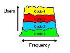
Some points to be noted from the above diagram:
–
All users share the
same BW.
–
Users are separated
by a code, not a timeslot or frequency.
–
Each user is spread
in the frequency domain
–
At the receive end,
users are de-spread using their own unique code.
– The user axis shows the strength of the
cumulative addition of signals transmitted by all users.
6. SPREAD SPECTRUM AND RADIO PROPOGATION
Introduction
The major concern in Wireless is digital communication is efficient use of Bandwidth and power. But there are scenarios where it is necessary to sacrifice the efficient use for design considerations. One such scenario is secure communication hostile environment. This design objective is met using a modulation technique called as Spread Spectrum (SS).
The advantage of using is its ability to reject interference .May it be intentional (some jamming transmission) or unintentional (in this technique signal of one user is interference to another user).
Defining Spread Spectrum
A complete definition to Spread Spectrum I feel is the one given by Haykins. I quote him below.
His definition is in two parts.
1. Spread Spectrum is a means of transmission in which the data sequences occupy a bandwidth in excess of the minimum bandwidth necessary to send it.
2. Spread Spectrum is accomplished before transmission through the use of a code that is independent of data sequences .The same code is used at the receiver to despread the received signal so that the original data sequence may be recovered.
Advantages of Spread Spectrum
1. Multipath rejection:
2. Multipath access: Number of users uses a common channel for communication.
Concept of Spread Spectrum
When the information bearing signal and a PN sequence is multiplied at a multiplier we obtain the desired modulation. The question is how do we get the increase spectrum? This is a simple Fourier Transform property. Multiplication in time domain is convolution in frequency domain. Hence by multiplying a narrow band information signal and a wideband code sequence, the multiplied signal will have the spectrum similar to the wideband PN code sequence.
How Spread Spectrum gives secure communication?
The spread signal gets the characteristics of the PN code sequence. This signal appears noise like to a receiver that has no idea about the spreading code.
Synchronization
The success to a CDMA system is proper synchronization. To despread a spread spectrum signal we need to use the same code used for spreading the signal. The operation takes place in two stages acquisition and tracking. First we have a acquisition or coarse synchronization is done, where we try to align the code in chips away from each other. In tracking or fine synchronization we measure the correlation and bring the receiver code in sync with the transmitted code.
Radio Propagation
The ideal communication channel model is a communication channel (bandwidth) corrupted with AWGN (i.e. Additive White Gaussian Noise). But in real the radio channel deviates from the ideal model due to the presence of multi-path.
Wireless communication is evaluated on 2 main points:
- Median Signal Strength
- Signal Variability
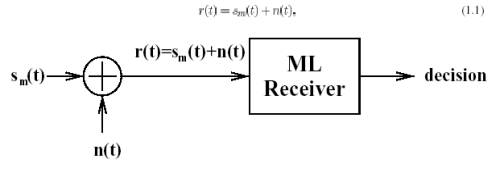
AWGN Channel Communication Model
s(t)
is information signal
n(t) is AWGN
7. Interesting History of Spread Spectrum
CDMA has its roots in pre World War 2 America. In 1940, Hollywood actress turned inventor Hedy Lamer and co-inventor George Antheil, with WW2 looming, co-patented a way for torpedoes to be controlled by sending signals over multiple radio frequencies using random patterns.
Despite all efforts by inventors to advance this technology from experiment to implementation, the US Navy discarded their work as architecturally unfeasible!
The idea which was known as frequency hoping and later as frequency hopping spread spectrum technique remained dormant until 1957 when engineers at the Sylvania Electronic Systems Division in Buffalo, NY took up the idea and the Lamarr-Antheil patent expired, used it to secure communication for the US during 1962 Cuban missile crisis.
After becoming an integral part of government security technology, the
US military, in the mids-80 , declassified what's has now become CDMA
technology, a technique based on Spread Spectrum technology.
8. Band of Operation
There are 2
CDMA common air interface standards:
–Cellular (824-894 MHz) - IS-95A
–PCS (1850-1990 MHz) - Joint-STD-008
These 2 standards are very similar in
their features, with exceptions of the frequency plan, mobile identities for
addressing, and certain message fields.
The carrier frequency
in CDMAOne requires 1.25Mhz Bandwidth.
Cellular Band
–45 MHz
spacing for forward & reverse channel
–Frequency assignments are on 30 kHz increments
PCS Band
–80 MHz spacing for forward & reverse channel
–Frequency assignments are on 50 kHz increments
9. Cell Configuration in CDMA
In Wireless communication we divide a whole geographical area into smaller chunks called cells. A single BS services each of these cells. These cells are grouped into groups of 3 –7 cells to form a cluster[1]. Groups of clusters are put under a single Base Station Controller (BSC). All the BSCs in PLMN are controlled by a MSC (Master Switching center). By repeating the 7-cell cluster over a city we can service the entire area by planning just one cluster.
To be frank planning cells for a city is a lot more complicated and elaborate task but on paper in ideal conditions this is a simple concept.
This hierarchy of cells helps
increasing capacity and easy of routing calls apart from other operational
advantages. But the final number of
cells a area is a compromies on factors like the density of calls ,number of
BSs , size of each cell ,capacity, the budget in hand etc.. Planning cells is
quite an interesting topic indeed and the final approved plan is a middle road.
As we have mentioned a cluster
, let me also take the oppurtunity to
mention the advantage of CDMA over other techniques like FDMA/TDMA. In the case of FDMA/TDMA a given spectrum would be divided into smaller
chunks , each of this chunks uniquely assgined to a cell in a cluster. By
repeating this pattern a big city is
serviced by the limited spectrum.
Smaller bandwith for trasnmission compromises
on quality of signal. This planning of frequencies is called Frequncy Planning. This
distribution of frequncies in a cluster
is important to combat
co-channel inteference and adjacent channel inteference between
repeating clusters
In CDMA, freqeuncy planning is minimal. The entire spectrum can be assigned to all the 7 cells in the cluster. This is possible because of the orthogonal property of the unique codes used for transmission. As a consequence, usage of the entire spectrum enhances the quality of voice. Adjacent channel interference is combated by power control (we will discuss this later) and planning of Walsh codes in use at the BSC level.
10. Environment around the Mobile Station
Information flows from the BS to the MS via the forward channel or the forward link and from the MS to the BS via the reverse channel or reverse link. Before going any further lets see all types of codes that we will come across. Let’s digress for a while.
Walsh, Short PN and Long PN Codes
Walsh Codes
We first came across the unique codes for spreading. These special codes are called Walsh Codes. In each cell, a user has a dedicated Walsh Code. These codes are follow the orthogonal property of vector i.e. auto-correlation of a code is 1and correlation with any other code is 0.More about its use later. In IS-95A and IS-95B we use 64 orthogonal codes and in CDMA-2000 we use 128 orthogonal codes. These codes are also used for spreading on a forward link. Hence the understanding now is that the forward link is divided into as many Walsh Codes and called a Code Channel. On the reverse link the Walsh Codes are not used to differentiate users but for 64-ary modulation.
Short PN Code
. This is a 16 bit short PN Code used to identify the BS and hence the cell. Distinguishing of the different BS is done by assigning an offset of this code to a common time reference to each BS in the network. On the reverse link the mobile uses the code for extra signal robustness, but without any offset. Services of the GPS ( Global Positing System) are used in synchronizing the various offsets of BS in the network.
Long PN Code
This code on the reverse link is used for spreading meaning identifying the mobile station. It is 42-bit code. On the forward link it is used for data scrambling.
Note:
Lets discuss from now on IS-95A and IS-95B and take the delta portion covering CDMA-2000 later. Understanding will be clearer since it is a evolutionary standard from IS-95A to CDMA-2000.
IS-95 Logical Channels
Now coming back on track.
Forward Link
The
Forward CDMA link consists of up to 64 logical channels (code channels). A code channel is one of a set of 64 so-called
Walsh functions. The Walsh makes the channels completely separable in the
receiver. • Each forward code channel is
spread by the Short Code (short PN code) , which has I- and Q-components. The
two coded, covered, and spread streams are vector-modulated
on the RF carrier. The spreading modulation is thus QPSK, superimposed on a
BPSK code symbol stream.
The Forward Link is divided into 64 code channels. The logical structure is described below.
Pilot Channel:
This channel is all
zeros – carrying no data information. This channel is the beacon channel
that defines the radius of the cell and hence is transmitted with the largest
power. It is used as
a
timing source in system acquisition and as a measurement device during handoffs
(MAHO).. The pilot channel is
assigned W0.
The
period of the pilot short
code, 215= 26.67 ms at the 1.2288 MHz chip rate. The pilot
phases are assigned to BS in multiples of 64 chips, giving a total of 215/ 64= 512 possible assignments. Hence this 9-bit number (512 assignments) identifies the pilot phase assignment is
called the Pilot Offset
Synchronization Channel:
Used by the mobile during system
acquisition to receive the system time, system identification and parameter information and state of the
Long Code. Sync Channel is W32. This
operates at 1200 bps.
Paging Channel:
This channel carries overhead
messages, pages, call setup messages and orders. The bps (4800 or
9600bps) of this channel is got from the Sync. Channel. The paging channel is assigned Walsh codes W1-W7. W1 is called the
primary paging channel and overhead messages are always transmitted on the
primary PCH. It operates in slotted-mode (mobiles ‘sleep’ and ‘wakeup’ when
it’s time to listen).
Traffic Channel:
The traffic channels are assigned to individual users to
carry call traffic. All the remaining Walsh codes are available, subject to
overall capacity limited by noise.
To conclude a Forward
Channel is identified by:
– Its CDMA RF carrier Frequency and
– The unique Short Code Piltot Offset of the sector and
– The unique Walsh Code of the user
Reverse Link
•Reverse CDMA Channel
consists of 2 42-1 logical channels. One of the logical channels is permanently and uniquely
associated with each MS. The channel does not change upon handoff.
•The reverse CDMA Channel does not follow the strict orthogonal rule
strictly uses a very long period spreading code, in distinct phases. The
correlations between mobile stations are not zero, but they are acceptably
small.
Access Channel:
Access channels
are used by mobiles not yet in a call; to transmit registration requests, call
setup requests, page responses, order responses, and other signaling
information. An access channel is really just a public
long code offset unique to the BTS sector. Access channels are paired to Paging
Channels. Each paging channel can have up to 32 access channels. These channels
operate at 4800 bps.
Reverse Traffic Channel:
The reverse traffic channel are used by individual users during their actual calls to transmit traffic to the BTS .A reverse traffic channel is really just a user-specific public or private Long Code mask
The contents of the long code mask for Access Channel and Reverse
traffic channel are derived as shown in the diagram below:
For Access Channel
|
110001111 (9 bits) |
Access Channel Number (5
bits) |
Paging Channel Number (3
bits) |
Base Station Identification (16
bits) |
Pilot Offset of Forward Channel (9 bits) |
For Reverse Traffic Channel
|
1100011000 (9
bits) |
Permuted
ESN (32 bits) |
ESN=(E31, E30, E29, E28, E27, E26, E25… E2, E1, E0)
Permuted ESN=(E0, E31, E22, E13, E4, E26, E17, E8, E30, E21, E12, E3, E25, E16,,E7, E29, E20, E11, E2, E24, E15, E6, E28, E19, E10, E1, E23, E14, E5, E27, E18, E9)
ESN is a 32 bits unique number assigned by the manufacturer of the mobile.
When a call is setup a
user gets a pair of Forward/Reverse Traffic Channels.
To conclude A Reverse Channel is identified by:
–
Its CDMA RF carrier Frequency and
–
A unique Long Code PN Offset of the individual handset
11. IS-95 Physical Layer
Forward Link
The user data is spread to a channel chip rate of 1.2288MHz. IS-95 uses a different modulation and spreading technique for the forward and reverse links. On the forward link, the base station simultaneously transmits the user data for all mobiles in the cell by using different spreading sequence for each mobile. The user data is encoded, interleaved, and spread by one of sixtyfour
orthogonal spreading sequences (Walsh functions). To avoid interference, all signals in a particular cell are scrambled using a pseudorandom sequence of length 215 chips.
The modulation on the Forward link is shown above. The output chips are fed into the modulator. Modulation is discussed in the next section.
The forward link is organized into pilot, sync, paging and traffic channels.
–
Pilot channel is a stream of zeros spread by W0 at 1.22888Mcps.
– Sync Channel: Information bits are fed into the Convolutional Encoder at 1200 bps and spread at 1.288Mcps by W32.
– The Paging Channel: Information bits are fed into the Encoder at 4K8 0r 9K6 bps and scrambled by a long code sequence before being channelized by the right Walsh code (W1-W7).
– The forward traffic channel: Rate Set 1 (RS1) or Rate Set 2 Information bits are fed into the encoder and scrambled by a public or private long code ( in case of voice privacy) and is than channelized by the assigned Walsh code before being send to the modulator.
Reverse Link
On the reverse link, all mobiles respond in an asynchronous fashion. The user data is encoded, interleaved, and then blocks of consecutive. 6 bits are mapped to one of the 64 orthogonal Walsh functions. Once the Walsh code is identified is 64 bits that make up the code are output at a rate of 307.2 kHz.. Since the mobile is not transmitting a pilot signal on the reverse link (unlike the forward link), coherent detection is not possible. As a result, the base station receiver may correlate the received signal with all of the 64 possible Walsh codes and determine a peak correlation to determine which code was sent. This operation does not require an estimate of the channel amplitude, which the Pilot channel gives in the forward link. Finally, the data is spread by a user specific code, which is 42-bit (channel identifier) before sending it to the modulator
. Modulation is taken in the next section. The reverse channel is organized in access channels and traffic channels.
Formation of chips on the Reverse link is shown below.
–
Access channel bits
come into the 1/3 Convolutional Encoder •at 4800 bps. The output bit stream is hash mapped in block of 6 bits on
a 64X64Walsh matrix. The selected Walsh code is than spread by the access
channel long code mask.
–
On the reverse
traffic channel the information bits come into the 1/3 Convolutional
Encoder •at 4800 bps. The output bit stream
is hash mapped in block of 6 bits on a 64X64Walsh matrix. The selected Walsh
code is than spread by the user specife long code mask. This can be a public
(computed on the basis of permuted ESN) or private ( in case of voice privacy).
12. Modulation used in CDMA Systems
Mobile Stations
CDMA mobiles use offset QPSK modulation. The Q-sequence is delayed half a
chip, so that Q and I never change simultaneously and the mobile TX never
passes through (0,0). This is done since while demodulation is it always wanted
to have a uniform envelope and abrupt changes in the envelope may cause to have
spurious components in the demodulated wave.
Modulation Parameters on the Reverse
Link
–
20
ms interweaver for time diversity
–
Orthogonal
64-ary Walsh modulation symbols
–
Long
code of period 2 42 -1 (for channel
identification) concatenated with PN codes of length 2 15.
–
No
coherent OQPSK
–
Diversity
o
Time
diversity: coding + interleaving
o
Path
diversity: RAKE receiver
o
Spatial
diversity: 2 Rx antennas (4 Rx antennas available during handoff)
Base Stations
CDMA base stations use QPSK modulation every signal (voice, pilot, sync,
paging) has its own amplitude, so the transmitter is unavoidably going through
(0,0) sometimes; no reason to include 1/2 chip delay
Modulation Parameters on Forward link
–
64
orthogonal Walsh codes per sector to identify channels
–
Long
code (period 2 42 -1) to scramble data
–
DS-SS
at 1.2288 Mcps
–
Every
cell uses the same PN sequence (period 2 15 or 26.67ms) and is identified by a pre-defined offset (64 x n chips)
–
Coherent
QPSK demodulation
–
Diversity
o
Time
diversity: coding + interleaving
o
Path
diversity: soft handoff and RAKE receiver
13. Power Control in CDMA Systems
CDMA is an Interference Limited System
CDMA is an interference-limited system. Having made this statement let us dwell on this. The success of the system lies in controlling the total power in the CDMA system.
In a CDMA environment every MS (i.e. a handset) is a source of noise to the other. At the receiver at the MS sees the radio environment around it as a cumulative addition of information for itself and interference. The interference is information for other MSs plus noise from others sources. Hence if the interference is more, the information signal cannot be retrieved.
A mobile has a special receiver called a RAKE receiver that can make estimates of multipath fading and retrieve the information for a particular mobile. The simple mathematical steps outline how the receiver works.
SI(t) Information signal for Ith mobile
WI(t) Walsh Code for Ith mobile
R (t) Received signal at RAKE receiver
Hence at any RAKE receiver the received signal will be (assuming no multipath fading)
R (t) = S SI(t)Å WI(t)
Let’s us retrieve the signal for user1
W1(t) Å R(t) = W1(t) Å S SI(t)Å WI(t)
= S1(t) + 0
The orthogonal property of Walsh Codes makes zero the noise and retrieves the signal.
Hence if noise or interference is more it will blind the receiver .So we need power control.
NEAR / FAR Problem
A user close to a cell would saturate the receiver and eliminate all users further away, unless the power is controlled. This is Near /Far problem
CDMA Capacity
The CDMA Capacity is given by the following expression:
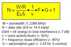
Points to Take Note:
1. Power Control prevents Near/Far problem
2. Increases CDMA system capacity
Hence in the CDMA system we do power control on both the forward and reverse link.
Forward Link Power Control
The BS uses Closed Loop Power Control on the forward link. The mobile station periodically informs the BS to increase or decrease its power.
Reverse Link Power Control
We have two types here:
1.
Open Loop Power
Control
The Open Loop Power Control is used during access attempts. It increases the power during each attempt. If you are now thinking that such attempts may disturb the communication by increasing power at the BS receiver. Well this does not happen, since BS has already informed the power increment step on each attempt to MS on a broadcast mobile.
2. Closed Loop Power Control
In Closed Loop Power Control there is a feedback procedure. This type of power control is used when the MS is using the traffic channel resources i.e. it is active. The BS is continuously monitoring the reverse link. If its find the quality of the reverse link poor than it will instruct the mobile to increase its power by inserting power control bits in traffic data. This insertion of power bits for power control is called Bit Puncturing. The BS does this every 800 b/s.
14. CALL PROCESSING
Call processing is the complete process of routing, originating, terminating cellular telephone calls, along with the necessary billing processes. Here we shall introduce call processing from the MS perspective, understanding the states of the MS and the functions it can carry out being in each of these states.
The CDMAOne mobile goes through 4 states from power-on to getting in call. The diagram below captures this in great detail also giving details about conditions, which cause state transition. Each state shall now be handled in more detail (the error conditions have not been shown).
The
Mobile Station States are
1. MS Initialization
2. MS Idle State
3. System Access State
4. MS Traffic State
MS-Initialization State
When the MS is powered-on, it enters the MS-Initialization state with a power-up indication. In this state it performs cell search and carrier detection, finally camping on to a cell.. Once t has camped on to a cell it listens to the Primary paging channel in the Ms-Idle state. The state has MS-Initialization has 4 sub-states where the mobile performs in which it performs all the vital functions before entering the MS-Idle State. The detailed diagram below illustrates all the sub-state changes.
The Mobile Station Initialization State consists of the
following sub states:
System Determination Sub state -The mobile station selects which system to use. Enters the next state if the selected system is a CDMA system.
Pilot Channel Acquisition Sub state -The
mobile station acquires the Pilot Channel of a CDMA system. The MS shall tune
to the CDMA Channel number in CDMACH and search for Pilots. Goes to the next
state if it acquires the Pilot in T20ms.
Sync Channel Acquisition Sub state -The mobile station obtains system configuration and timing information for a CDMA system. On entering this state the mobile shall set the code channel to W32.The mobile shall wait for a valid Sync Channel for T21ms.It than goes to the next state if MOB_P_REV is greater than the MIN_P_REV in mobile. It update the following parameters from the Synch Channel Message:
The following values are updated
from the Sync Channel Message:
Protocol revision level (P_REVs = P_REVr)
Minimum protocol revision level (MIN_P_REVs =
MIN_P_REVr)
System identification (SIDs = SIDr)
Network identification (NIDs = NIDr)
Pilot PN sequence offset (PILOT_PNs = PILOT_PNr)
Long code state (LC_STATEs = LC_STATEr)
System Time (SYS_TIMEs = SYS_TIMEr)
Paging Channel data rate (PRATs = PRATr)
Timing Change Sub state -The mobile station synchronizes its timingg to that of a CDMA system.
All mobiles maintain a PRL (Preferred Roaming List given by service provider), which along with the History list is used in selecting a carrier. The PRL is a guiding list of carriers, which are permitted and forbidden to the subscriber.
MS-Idle state
The MS enters this state and listens to the Primary Paging Channel with the PRAT read from the Sync channel message. Any kind of interrupt say from the User, such as sending a SMS, making a call or network paging causes the Mobile to leave the idle to enter the System Access State. Calling this state, the Idle state is a misnomer as the mobile is busy but appears Idle to the user. We shall discuss this state in detail now.
What does the mobile do being in this Idle State?
The name given to this state is a misnomer. Actually the
mobile is very busy in this state. In short the mobile constantly turning parts
of itself on and off; on to perform vital functions and off again to save power
so that the battery lasts longer. This periodic on and off of the mobile
transceiver is called slotted mode of operation.
Note:
The mobile can operate in the slotted mode only in the idle state. While a mobile is latched to a particular network, for most of the time is in the idle state. Being in this state the mobile monitors the Paging Channel. If there is a procedure that requires to be carried out for a message received on Paging Channel, the mobile enters the System Access State. Paging Channel messages or user actions can cause the mobile to go from idle state to System Access State. So in this state the mobile station can receive messages, receive an incoming call (mobile station terminated call), initiate a call (mobile station originated call), initiate a registration, or initiate a message transmission.
Idle Procedures
The mobile station performs various procedures for messages received on Paging Channel. They are as follows.
- Paging Channel monitoring procedures. The mobile monitors the Paging Channel in the slotted or non-slotted mode of operation. In slotted mode of operation the mobile monitors all the slots in the paging channel.
- The mobile station performs acknowledgement procedures. Acknowledgements of messages received on the Paging Channel shall be sent on the Access Channel. When sending a message that includes an acknowledgement, the mobile station shall set the VALID_ACK field to '1' and shall set the ACK_TYPE and ACK_SEQ fields equal to the ADDR_TYPE and MSG_SEQ fields, respectively, of the message being acknowledged. When sending a message that does not include an acknowledgement, the mobile station shall set the VALID_ACK field to '0' and shall set the ACK_TYPE and ACK_SEQ fields equal to the ADDR_TYPE and MSG_SEQ fields, respectively, of the last message received that required acknowledgement. If no such message has been received, the mobile station shall set the ACK_TYPE field to '000' and shall set the ACK_SEQ field to '111'.
- The mobile performs Registration procedures. Please see the section on Registration for more information.
- In idle state the mobile can perform an idle handoff( An idle handoff occurs when a mobile station has moved from the coverage area of one base station into the coverage area of another base station during the Mobile Station Idle State).
- The mobile shall perform the Response to Overhead Information Messages. The overhead messages are System Parameters Message, CDMA Channel List Message, Extended System Parameters message, Neighbor List Message, Global Service Redirection Message, and Access Parameters Message. Other than the last message all are called configuration messages. Associated with the set of configuration messages sent on each Paging Channel is a configuration message sequence number (CONFIG_MSG_SEQ). When the contents of one or more of the configuration messages change, the configuration message sequence number is incremented. For each of the configuration messages received, the mobile station stores the configuration message sequence number contained in the configuration message. If the configuration sequence number changes the mobile ahs to update the values received in the configuration messages. The Access Parameters is tagged by the ACC_MSG_SEQ.
- The mobile station can do Origination operation. If the user initiates a call.
- The mobile station can do a Message Transmission if the users direct the mobile to transmit a message.
- The mobile station has to responds to Page Messages. The Page Messages are General Page Message, Page Message and Slotted Page Message.
- The mobile station had to respond to message or order received other than Page Messages.
- Power down operation whenever the user directs the mobile to do so.
"Idle" phone is plenty busy!
I said earlier that in the idle state the phone is busy. Let us go about seeing how the mobile station is busy. See what the mobile does when is busy in a real environment? The most important thing the mobile does is to wake periodically and turn on its receiver briefly to see if it has been paged, which means to find out if there is an incoming call (mobile termination call) or a message. This happens on what is known as a slot cycle, and the base station controls the period of the slot cycle. Recall this is Slotted mode of operation Slot cycle indices are numbers from 0 to 7, and for any index the period is 1.28 seconds multiplied by 2^index.
Note:
The receiver consumes quite a lot of power. Relatively speaking the purpose of the slot cycle is to permit the phone to keep the receiver turned off most of the time. This is vital to extend battery life.
When the mobile first registers with a base station, the base station and mobile determine which paging channel the mobile will use (if there is more than one) and what phase of the slot cycle that mobile will use. Thereafter, the phone wakes periodically, turns its receiver on briefly to see if it has an incoming call or if there is other traffic from the cell it must respond to, and if there is nothing then it shuts the receiver down again and waits until the next slot time. This is slotted mode of operation.
When an incoming call arrives at a base station for a given mobile, the phone system of the caller generates the sound of a phone ringing as a comfort tone back to the caller (this tone comes in Alert With Information Message), and the base station waits until the slot time for the called mobile. When it comes around, the cell sends a message to the phone telling it that there is an incoming call. This causes the phone to waken and set up the call, and to begin to ring. If the phone doesn't respond to the page, the cell may try again on the next slot.
Note:
The advantage of a longer slot cycle is that the phone spends a lower percentage of the time with its receiver on and thus the battery will last longer. It also means there is more capacity on the paging channel. The advantage of a shorter slot cycle is that the phone gets more chances to receive the page, and will receive the page sooner.
The mobile also has to perform Registration, to keep informing the base station what is its current location. More details on this in the Registration section.
MS-System Access State
The MS enters this state on indications as received from the idle state to request resources from the network. This shall get clearer by studying the diagram on sub-states below. The MS transmissions are in the slotted ALOHA mode, which is based on fair contention on the air interface. This behaviour of the mobile on the air interface is controlled by the parameters in Access Parameter Message received as a part of Configuration Messages. All transmissions are under the Open Loop Power control.
The MS moves to a traffic channel on receiving the Channel Assignment Message. In short this state is a transition from idle to connected mode, wherein the network has not committed resources to the MS. Once the network realizes that the requests can be accommodated the mobile is allocated a traffic channel.
The diagram below explains the sub states in the state.
Power control in System Access State
We shall now discuss the phone operation in on access channel little more in detail. As earlier said that Power Control is necessary for efficient operation in a CDMA system. Information transmitted in the System Access state is of bursty nature and there is no scope of power control since the MS is not set-up on a dedicated link with the BS. Hence in this case the power control in use is the Open Loop power control.
The basis of this power control is setting up the mobile with parameters that make it transmit at intervals, which prevent collisions from other mobiles by using a hash equation (which has minimum collisions). The hash equation uses some general parameters received in the Access Parameters message (APM) and parameters, which are unique to the mobile.
Phone operation on Access Channel
The MS transmits access probes to the BS with increasing power levels in a probe sequence. A bunch of 15 such probe sequences is called an access attempt. The power increment between probes, time interval between probes and sequences are all set from values obtained in the APM.
A typical Access Parameter Message looks like this:
The following variables control phone behaviour on the access channel. These are obtained from the parameters sent on the Access Channel Message as shown below.
|
Variable |
Name |
Generation |
|
IP
|
Initial
Open-Loop Power |
IP=
-73-Mean Input Power( dBm ) + NOM_PWR + INIT_PWR |
|
PD |
Persistence
Delay |
Delay
continues slot by slot until persistence test passes |
|
PI |
Power
Increment |
PI=PWR_STEP |
|
RA
|
Access
Channel Number |
Random
between 0 and ACC_CHAN; generated before every sequence |
|
RN
|
PN
Randomization Delay |
Hash
using ESN between 0 and 2^(PROBE_P_RAN)-1;generated once at the beginning of
the attempt |
|
RS |
Sequence
Back off |
Random
between 0 and 1 + PROBE_BKOFF; generated before every sequence( except the
first sequence) |
|
RT
|
Probe
Back off |
Random
between 0 and 1 + PROBE_BKOFF; generated before subsequent probes |
|
TA
|
Ack
Response Timeout |
TA=
80 x (2 + ACC_TMO); timeout from end of slot |
The parameters in the above table are used in the access iteration shown in the flow chart below.
The above diagram is recommended for study to understand phone operation on the access channel.
MS Control on Traffic Channel State
The mobile enters this state from the System Access State either to originate or answer a call. Apart from this mobile may come to the traffic state either to send/receive a long SMS or OTASP procedures depending on the Service Option in the Origination Message/Page Response Message.
The state machine in the traffic state is shown below.
The MS enters the traffic state either when it has placed a call or to enter a call. The flow sequence is different for these 2 cases. The blue arrows and orange arrows give transitions in the MT /MO call scenario respectively. The back arrows give common flow after the mobile has entered the Conversation sub state.
After call release the Ms enter the System Determination sub state with the appropriate indication.
15. MESSAGE FLOW SEQUENCE IN CALL SETUP
In this section we shall discuss some common scenarios. Important fields of the messages have been added for detail.
Placing a Call
Step 1 MS -> BS
The mobile user dials the numbers and presses the SEND button causing the mobile to transmit an Origination Message on the access channel.
ACH: Origination Message
ACK_SEQ: 7
(acknowledgment sequence number = mod 8)
MSG_SEQ: 6 (message
sequence number)
ACK_REQ: 1 (ack
required)
VALID_ACK: 0 (this
message is not acknowledgment to previous msg)
ACK_TYPE: 0
IMSI: 123-456-789
AUTH_MODE: 0 (no
authentication fields)
SLOTTED_MODE: 1
Service option: (6) Voice (13k)
PM: 0 (voice privacy not
supported)
Chari: 9845437248
Step 2 MS <- BS
The BS acknowledges receiving the origination by sending a BS Acknowledgement on the paging channel.
PGCH :ORDER Message
ACK_SEQ: 6
MSG_SEQ: 0
ACK_REQ: 0
VALID_ACK: 1 (message is a
acknowledgment to a previous message)
ORDER: Base Station
Acknowledgement Order
Step 3 MS <- BS
The system arranges the resources for the call and starts transmitting (NULL frames) on the traffic channel. The BS notifies the mobile in a Channel Assignment Message on the paging channel and the MS goes to a traffic channel.
PGCH: Channel Assignment
Message
ACK_SEQ: 6
MSG_SEQ: 1
ACK_REQ: 0
VALID_ACK: 0
IMSI: 972-849-5073
ASSIGN_MODE: Traffic Channel
Assignment
GRANTED_MODE: 2
CODE_CHAN: 12
ENCRYPT_MODE: Encryption
disabled ( since authentication was not performed hence no encryption)
BAND_CLASS: PCS band
CDMA_FREQ: 425
Step 5
The mobile on receving atleast 2 NULL frames concludes that it is on the right TCH.The MS and BS acknowledgment each other’s traffic channel acknowledgment messages. Now the mobile is on Traffic Channel.
Step 6
MS <- BS
PGCH: Order Message
ACK_SEQ: 7
MSG_SEQ: 0
ACK_REQ: 1
ENCRYPTION: 0 (no encryption
of type-specific fields)
ORDER: Base Station
Acknowledgement Order
Step 7 MS -> BS
ACH: Order Message
ACK_SEQ: 0
MSG_SEQ: 0
ACK_REQ: 0
ENCRYPTION: 0
ORDER: Mobile Station
Acknowledgement Order
Step 8 MS <- BS
The base station and the mobile negotiate the type of call .In this case voice ( 13K). Service Negotiation takes place.
FTCH: Service Connect Message
ACK_SEQ: 7
MSG_SEQ: 1
ACK_REQ: 1
ENCRYPTION: 0
Forward Traffic Channel Rate
(Set 2): 14400, 7200, 3600, 1800
Reverse Traffic Channel Rate
(Set 2): 14400, 7200, 3600, 1800
Service option: (6) Voice
Forward Traffic Channel:
Primary Traffic
Reverse Traffic Channel:
Primary Traffic
MS -> BS
RTCH: Service Connect Completion
ACK_SEQ: 1
MSG_SEQ: 0
ACK_REQ: 1
ENCRYPTION: 0
MS <- BS
FTCH: Order Message
ACK_SEQ: 0
MSG_SEQ: 0
ACK_REQ: 0
ENCRYPTION: 0
ORDER: Base Station
Acknowledgement Order
The audio circuit is completed and the mobile caller hears ringing
Paging a Mobile for an Incoming Call
Step 1
In the idle state the mobile monitors the paging channel to receive incoming calls.A General Page Message on the Paging Channel notifies an incoming call.
BS - > MS
PCH: General Page Message
MSG_SEQ = 1
IMSI_S = 9876543210
SERVICE_OPTION = 2
Step 2
The paged mobile sends a Page Response Message on the access channel.
BS <- MS
ACH: Page Response Message
ACK_SEQ = 1 MSG_SEQ = 2 ACK_REQ =
1 VALID_ACK = 1 ACK_TYPE = 2
MSID_TYPE = IMSI and ESN
ESN = 0xDEADBEEF IMSI_S =
9876543210
AUTH_MODE = 1 (authentication
fields included)
AUTHR = 0x307B5 (authentication signature)
RANDC = 0xC6 (global random number in APM)
SERVICE_OPTION = 2
PM = 0 (voice privacy not supported)
Step 3
BS -> MS
PGCH: Order Message
ACK_SEQ = 2 MSG_SEQ = 0
ACK_REQ = 0 VALID_ACK = 1
ORDER = Base Station Acknowledgement Order
Step 4
The system sets up a traffic channel for the call, and sends a Channel Assignment Message.
BS -> MS
PGCH: Channel Assignment
ACK_SEQ: 2 MSG_SEQ: 1
ACK_REQ: 0 VALID_ACK: 1
ASSIGN_MODE: Traffic Channel
Assignment
GRANTED_MODE: 2
CODE_CHAN: 40
ENCRYPT_MODE: Encryption
disabled for type specific fields.
BAND_CLASS: 800M cellular
CDMA_FREQ: 347
Step 5
The mobile and the base station notice each other’s traffic channel signals and confirm their presence by exchanging Acknowledgment messages.
BS -> MS
RTCH: Order Message
ACK_SEQ: 0 MSG_SEQ: 0
ACK_REQ: 0
ENCRYPTION: 0
Step 6
BS <- MS
FTCH: Order Message
ACK_SEQ: 7 MSG_SEQ: 0 ACK_REQ: 1
ENCRYPTION: 0
ORDER: Base Station Acknowledgement Order
Step 7
The base station and the mobile negotiate the type of call eg. 13k voice, etc. Service Negotiation take palce.
BS -> MS
FTCH: Service Connect Message
ACK_SEQ: 7
MSG_SEQ: 1
ACK_REQ: 1
ENCRYPTION: 0
Forward Traffic Channel Rate
(Set 2): 14400, 7200, 3600, 1800
Reverse Traffic Channel Rate
(Set 2): 14400, 7200, 3600, 1800
Service option: (6) Voice
Forward Traffic Channel:
Primary Traffic
Reverse Traffic Channel: Primary Traffic
BS <- MS
RTCH: Service Connect Completion
ACK_SEQ: 1
MSG_SEQ: 0
ACK_REQ: 1,
ENCRYPTION: 0
Step 8
BS -> MS
The mobile is made to ring to present the user an Incoming call display using the Alert With Information Message.
FTCH: Alert With Information
ACK_SEQ: 3 MSG_SEQ: 1
ACK_REQ: 1 ENCRYPTION: 0
SIGNAL_TYPE = Alerting
ALERT_PITCH = Standard
SIGNAL = Long
RECORD_TYPE = Calling Party
Number
NUMBER_TYPE = National Number
NUMBER_PLAN = Telephony
Numbering Plan
PI = Presentation Allowed
SI = Network Provided
CHARi = 9845437248
BS < -MS
Acknowledging the previous
message.
RTCH: Order
ACK_SEQ: 1 MSG_SEQ: 4 ACK_REQ: 0
ENCRYPTION: 0
ORDER: Mobile Station
Acknowledgement Order
Answering a Call
This Connect Order is sent when the user presses the ANSWER key. This is a continuation from the previous flow.
BS <-MS
RTCH: Order Message
ACK_SEQ: 6 MSG_SEQ: 0 ACK_REQ: 1
ENCRYPTION: 0
ORDER: CONNECT ORDER
Acknowledging the previous message.
BS -> MS
FTCH: Order
ACK_SEQ: 0 MSG_SEQ: 1
ACK_REQ: 0
ENCRYPTION: 0
ORDER: BASE STATION
ACKNOWLEDGMENT
< === AUDIO LINK === > has been set up.
Releasing Call
This scenario can happen either from the MO (calling) or MT (called) end.
MS -> BS
Release order is sent to the BS when the User presses the DISCONNECT button.
RTCH: Order
ACK_SEQ: 1 MSG_SEQ: 1 ACK_REQ: 1
ENCRYPTION: 0
ORDER: MOBILE RELEASE ORDER
(normal)
MS <- BS
FTCH: Order
ACK_SEQ: 1 MSG_SEQ: 2
ACK_REQ: 0
ENCRYPTION: 0,
ORDER: Base Station Acknowledgement Order
MS<- BS
FTCH: Order
ACK_SEQ: 1 MSG_SEQ: 3
ACK_REQ: 0
ENCRYPTION: 0
ORDER: Release Order (no
reason given)
At the end of the call the mobile enters the SDS sub state.
16. HANDOFF
In this section we have to remember the Pilot Channel. It is like a lighthouse to a ship. It acts as a beacon for the mobile and identifies the BS. When the MS powers on it gets latched to a BS by searching for the Pilots. Now which pilot does it latch on to or say which BS does it latch to? Obviously it has to latch to the BS, which is nearest to it. So how does the MS know which BS is the nearest. Well, the MS will scan for the strongest (in terms of power) Pilot Channel and latch to it.
Now why handoff? When the MS goes from one cell to another cell Handoff occurs. As the MS goes away from the BS the power level of the pilot channel may decrease and hence it looks for a pilot of stronger strength to latch on.
This is to ensure that when a mobile station is using traffic channel resources, the information flow does not stop when control goes from one base station to another base station. Thus we prevent Call Dropping.
At this point there may be another question tickling you? Does the mobile station scan all the short PN offsets to search for a Pilot during handoff? Well, Pilot channels having the largest power; the mobile station from its position will receive varying power levels of different offsets. Here let me introduce the term Pilot Databases.
Pilot Databases
The Pilots are divided into sets, which are used to search for pilots during Handoff. The mobile maintains four sets:
1. Active Set: Pilots associated with forward traffic channels assigned by the base station
2.
Candidate Set:
Pilots not currently in the Active Set, but
whose level is high enough to be there (but others are stronger)
3.
Neighbor Set: Pilots that are not currently in the Active Set
or Candidate Set and are likely candidates for handoff. The initial neighbor
list is sent to the mobile in the System Parameters Message on the Paging
Channel.
4.
Remaining Set: Includes all pilots in the system which are not
in another set
Handoff Procedures
We have different types of Handoff Procedures depending upon the situation
1. Soft Handoff: Soft Handoff is when the mobile goes from one cell to another cell but uses the same frequency. We also can have softer handoff when the mobile goes to a different sector within a cell.
2. Hard Handoff: Hard Handoff is when
i. MS is transferred between disjoint active sets
ii. CDMA frequency assignment change
iii. The frame offset changes
iv. When the mobile is sent from CDMA channels to analog voice channels.
3. Idle Handoff: When the Paging Channel is transferred from BS to another BS
4. Access Handoff: When the mobile sends the access attempts to another BS.
<< Put a figure >>
17. REGISTRATION
Registration is the process of a mobile associating itself with a
particular cell in a particular network. There are 9 types which of
Registration.
1.
Power on: when a mobile is turned on
2.
Power off: just before a mobile is turned off
3.
Timer-based: after a certain timer expires
4.
Distance-based: if the mobile moves to a further cell
5.
Zone-based: if a mobile moves in or out of a zone
6.
Ordered: base station requests the registration
7.
Parameter change: if the mobile’s parameters change
8.
Implicit: base station infers the mobiles position
9.
Traffic channel: for registration in active mode
Of these the first five are autonomous type of registration. They are
called so, because the base station informs the mobile station at power on, to
register if any of the events happen.
18. AUTHENTICATION
Authentication is the
process by which information is exchanged between a mobile station and base
station for the purpose of confirming the identity of the mobile station. A
successful outcome of the authentication process occurs only when it can be
demonstrated that the mobile station and base station possess identical sets of
shared secret data. This is done so as to prevent what is called Phone Cloning.
The standards use the CAVE (Cellular Authentication Voice Privacy Encryption) Algorithm and CMEA[2] (Cellular Message Encryption Algorithm) for the maintaining security.
Uses of the CAVE and CMEA Algorithm
i. CAVE is also used to generate a set of cryptovariables for the Cellular Message Encryption Algorithm (CMEA) message encryption process.
ii. CAVE is used in the generation of 520 bits for the duplex voice privacy masks.
iii. CAVE is used in the generation of a subscriber's "shared secret data" from his unique A-key. Also used in verifying the manual entry of the A-key.
iv. CMEA is used in encrypting certain type specific fields.
When to carry out Authentication
Authentication is carried out under the following scenarios:
i. Registration
ii. Unique Challenge
iii. Origination
iv. Mobile Terminations
v. Data Burst Messages
Encryption
In an effort to enhance the authentication process and to protect sensitive information (example PIN’s sent as DTMF tones), certain fields which carry these sensitive information in Traffic Channel messages are encrypted.
19. Common Messages on the Air Interface
|
Access
Channel |
Paging
Channel |
|
Broadcast
Messages |
|
|
|
System Parameters |
|
|
Access Parameters |
|
|
Neigbhour List |
|
|
CDMA Channel List |
|
Call
Management Messages |
|
|
Origination |
Channel Assignment |
|
Page Response |
Page |
|
|
Release |
|
Data Burst |
Data burst |
|
Authentication
and Privacy Messages |
|
|
Authentication Challenge Response |
Authentication Challenge |
|
SSD Update Confirm/Reject |
SSD Update |
|
Base Station Challenge |
Base Station Challenge Confirm |
|
Mobility
Management Messages |
|
|
Registration |
Registration Accepted/Rejected* |
|
|
Registration Request* |
|
Operations
Messages |
|
|
|
Lock Until Power Cycle * |
|
|
Unlock * |
|
Other
Messages |
|
|
Mobile Station Reject |
|
|
Mobile Station Acknowledge |
Base Station Acknowledge |
|
|
|
|
|
|
|
Reverse
Traffic Channel |
Forward
Traffic Channel |
|
Call
Management Messages |
|
|
Connect |
Alert With Information |
|
Flash With Info |
Flash With Info |
|
Release* |
Release* |
|
Data Burst |
Data Burst |
|
Send Burst DTMF |
Send Burst DTMF |
|
Service Option Request* |
Service Option Request* |
|
Service Option Response* |
Service Option Response* |
|
|
Service Option Control* |
|
Authentication
and Privacy Message |
|
|
Authentication Challenge Response |
Authentication Challenge |
|
SSD Update Confirm/Reject |
SSD Update |
|
Base Station Challenge* |
Base Station Challenge Confirm |
|
Parameter Update Confirm* |
Parameter Update" |
|
Long code transition request* |
Long code transition request* |
|
long code transition response* |
long code transition response* |
|
Radio
Resource Management Messages |
|
|
Handoff Completion |
Handoff Direction |
|
|
Neighbour List update |
|
Pilot Strength Measurement |
Pilot Measurement Request |
|
Operations
Messages |
|
|
|
Lock Until Power Cycle * |
|
|
Unlock * |
|
Other
Messages |
|
|
Mobile Station Reject |
|
|
Mobile Station Acknowledge |
Base Station Acknowledge |
|
The * against a message
defines that they are of the type Order Messages. |
|
CDMA Message Structure
|
MSG_TYPE |
8 |
|
ACK_SEQ |
3 |
|
MSG_SEQ |
3 |
|
ACK_REQ |
1 |
|
VALID_ACK |
1 |
|
ACK_TYPE |
3 |
|
MSID_TYPE |
3 |
|
MSID_LEN |
4 |
|
MSID |
8 x MSID_LEN |
|
AUTH_MODE |
2 |
|
AUTHR |
0 or 18 |
|
RANDC |
0 or 18 |
|
COUNT |
0 or 4 |
|
REG_TYPE |
4 |
|
SLOT_CYCLE_INDEX |
3 |
|
MOB_PREV |
8 |
|
SCM |
8 |
|
MOB_TERM |
1 |
|
RESERVED |
6 |
|
CRC |
30 |
Typical IS95A Message PDUs on the Paging/Access Channel have the following fields as shown in the diagram.
|
MSG Length (8 bits) |
MSG_TYPE (8 bits) |
Layer 2 and Identification
Fields (8 fields) |
Common Authentication
Fields (4 fields) |
Reserved/specific to
Message |
CRC (30 bits) |
The Traffic channel PDU also has a similar structure. The CRC in Traffic messages in 16-bit unlike the 30-bit CRC in PCH/Ach messages.
The MSG_TYPE in CDMA2000 is split into a 2 bit PD (protocol discriminator) and a 6 bit (MSG_TYPE). This is backward compatible as the PD=00 for IS95A and 01 for CDMA2000.
Now let us fit the Access Channel Registration Message on the above-generalized PDU structure.
The
figure shows the Registration Message Structure, which is sent on the Access
Channel. A typical variable length PDU in IS-95A is shown on the left hand side
of the page.
Points
to Note:
- • MSG_TYPE that uniquely identifies a message and helps in parsing. In IS-2000 this 8-bit field is split into a 2-bit field PD (protocol descriptor) and 6-bit message identifier MSG_TYPE.In IS-2000 PD is (01) binary.
- Light Green Fields are the Layer 2 fields for flow
control. To ensure messages are not missed, all CDMA messages bear serial
numbers (MSG_SEQ) and important messages contain a bit requesting
acknowledgment (ACK_REG). The message number getting acknowledged is
returned in the ACK_SEQ. The message sequences work on MOD 8 counter.
- •Dark Green Fields: Addressing fields identify the
type of addressing to be used.
- Orange Fields: The common authentication fields help
to prevent spurious users from accessing the resources of the network. If
the values in the authentication fields match the values generated at the
BS, access is allowed. These fields shall be included be Authentication is
enabled in System Parameters Message.
- Sky Blue Fields: These are message specific fields.
Important fields of common messages are discussed in the Message flow
section
- Grey field: CRC is 3-bit number for Paging/Access
Channel and 16-bit for Traffic channel messages.
Overhead Messages
The
System Parameters and the Access Parameters messages are the 2 most important
messges of the 6 Overhead Messages. The other configuration messages are:
CDMA
List Message
Neigbhour
List Message
Global
Service Redirection and
Extended
System Parameter Messages.
Lest
discuss the contents in System Parameters and Access Parameters messages.
Notes:
–
The Pilot offset discussed earlier,is sent in each of
the confihuration messages to identify the BS of these messages .
–
The CONFIG_MSG_SEQ is checked by the MS .It this number is different from the stored number, it
means that the BS has changed the parameters and they have to be updated.
–
Fields POWER_UP_REG toREG_DIST determine the
Registrations the Ms has perform.
–
Parameters SCRH_WIN_A to T_TDROP are useful for taking measurements and handoff.
–
EXT_SYS_PARAMETER is 1 if an exteneded system parameter
message is in the configuration set of messages.
Notes
The fields of the access parameters message have been
discussed in the MS System Access Section.
20. IS-95B Enhancements
(To be included in Version 3)
21. CDMA-2000 Enhancements
(To be included in Version 3)
22. Glossary
Go to www.denbeste.nu/cdmafaq/glossary.shtml
23. Suggested Reading
24. References
25. About the Author
Rahul Chauhan is a protocol engineer and has been in the Telecom Industry for the last 3 years working on CDMA, CDMA1x, and GSM/GPRS protocols. Currently he is with UbiNetics; a PA Consulting company.
He also maintains a hobby site on wireless protocols: www.geocities.com/rahulscdmapage/.