 |
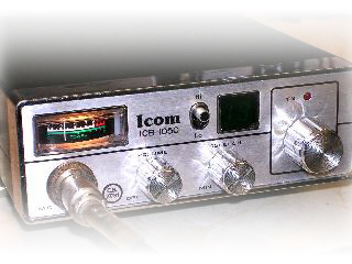
| JWR M2 / ICOM ICB-1050 AMATEUR 10M MODIFICATION |
| THESE FOUR STEPS FOR ICOM 1050 ONLY (Improves the Icom squelch) 1/ Remove diode from rear of board 2/ Change Resistor on rear of PCB to 220K 3/ Remove link R116 and fit 10K resistor 4/ Change C119 to a 0.47uF (Tantalium)+Ve to pin 12 THEN BELOW FOR BOTH THE RADIOS 1/ Change C228 to 30pf (Ceramic, VCO) 2/ Remove Green wire from IC 201 and put mauve wire in its place. 3/ Link pins 10, 11 and 12 together with one end of a 10K resistor and connect the other end of the resistor to pin 1 (+5v) Note. That is all what is required to get the rig onto 29MHz Remove C309 and C11 completely (Improves TX audio) Change C312 to 1000pF (680pF would do) Change C106 to 10 or 15pF (RX) That concludes all the changes. Other mods(REPEATER SHIFTS, MORE CHANNELS Etc.) can be done later if desired ALIGNMENT ---------------------- Hints; 1/ Be very careful with all the coils as they are filled with wax. Use a soldering iron to melt the wax before adjusting. 2/ RV101 alters the S meter reading and RV303 the deviation (mod) You my need to adjust these TO SET UP THE TX/RX but MAKE A NOTE OF THEIR SETTING and put them back as they were after set up. 3/ Dont forget to use a dummy load for TX 4/ Put a meter (10v range) +Ve lead on pin 8 (lock detector pin) of IC201, negative to ground and tune the VCO coil T202 (This coil is common to both TX and RX) wind the core down until 5v is achieved on both RX and TX. It might be worth having another 10m set without an antenna tuned to 29.600MHz near to the ICOM/JWR and have it TX'ing on channel 25 while you adjust it for maximum carrier on the 10m set. Then, still monitoring the carrier as described above, tune coils T207, T208, T209, T301, T302, T305 & T307 for maximum output. 5/ Now swop the two sets (and dummy load) and put the 10m set on low power TX while you tune coils T101, T102 & T103 on the CB for best signal NB. It is no longer a CB, so get your morse test passed ;o) |