 |
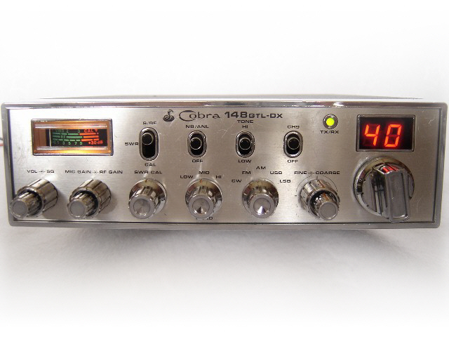
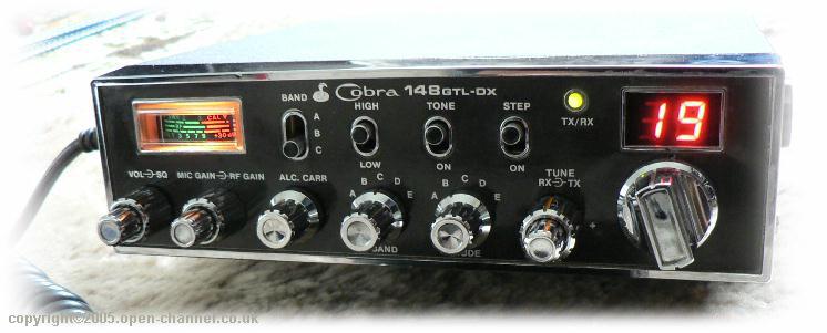
| Aaah the good old trusty Cobra 148GTL-DX. This radio was the baby to have in the early to mid 80's and its popularity was second to none. Running on the PC-879 (MK1) or PB-010 (MK2) Uniden Chassis it was quality all the way. Still very popular today and easy'ish to convert for those all important "extra" channels. The basic Cobra 148 GTL-DX was a 120ch Low/Mid/High AM/FM/USB/LSB/CW radio It had a "hidden" secret on the ch 9 switch. If you were on the high block on ch 40 (equivalent uk26) and put this switch "halfway" down you could get on the UK channels 30 and 31. The KC shift anti clockwise for 30 and fully clockwise for 31. (or was it 29 and 30) |
| updated SOON |

|
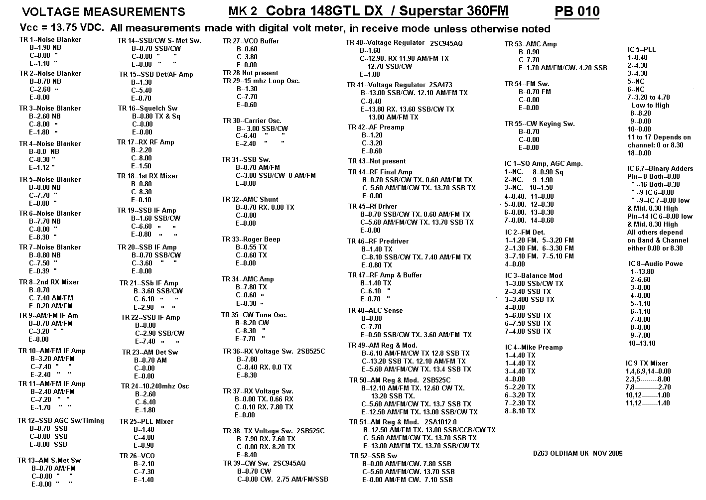
| Cobra 148GTL-DX Mk 2 / Superstar 360FM Mk 2 voltage measurements (right click - save picture as) |
| COBRA / S-STAR 010 CHASSIS 10KC Shift - Remove JP54 and put a 4k7 resistor in its place (located by IC6), then connect a wire onto pin 9 of IC6. Run the other end of the wire to a switch - then to a suitable 8v supply on the board. When the switch is thrown the rig will go up one channel (10KC's) 5KC Step - If you ground pin 6 of the PLL through a 10K resistor you will get an alternate range of 25.880MHz to 27.000MHz in 5K steps. |
| MANY THANKS TO DAVE DZ63 FOR HIS HELP IN SUPPLYING MOST OF THIS INFO. |
 |
| MK 2 COBRA 148GTL-DX TWO EXTRA BANDS, ONE ABOVE AND ONE BELOW MK2 SUPERSTAR 360FM With 6 switching diodes, three for each band, the radio will cover from 26.065MHz to 28.305MHz. Connect a diode to each pin 2 and 4 of IC6 and pin 6 of IC7. Connect all three diodes together and put a switch with +8v on it for 26.065MHz to 26.505MHz. For 27.865MHz to 28.305MHz connect the other 3 diodes to pin 2 of IC7 and pins 4 and 15 of IC6. Again join all 3 diodes together and wire to a switch with +8v on it. You may need to extend the VCO to get full coverage by adding 220pf to C96 (in Parallel) to the left of the VCO. To speed up the VCO locking time replace R125 2.2K for 1K |
| For 26.065MHz to 26.505MHz put the band switch to LOW band then switch the extra diodes on at switch A. For 27.865MHz to 28.305MHz put the band switch to HIGH band then switch the extra diodes on at switch B. |
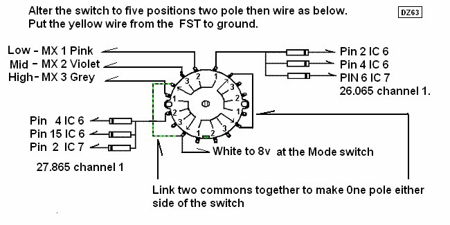
| How to open out the 3 position Bandswitch to 6 position Please read this in its entirity before attempting the job so you know whats expected. |
| Not a Cobra Radio but as it is a 'Uniden' type and there are no plans at the moment for a Stalker 9 page, I have put it here |
| Cobra 148GTL-DX MK2 modification to Final Transistor Info courtesy of Rick - Euro Radio Co. |
 |
| THE COBRA PROJECT Courtesy of Euro Radio & Zodiac Electronics, A CD full of information on the legendary Cobra 148 Mk1/2 |