The universe is a static class that can access all objects in a wire file or within Alias. The main feature of the universe is that it has a pointer to a tree-like data structure which is called a directed acyclic graph (DAG). All geometry, light, camera and cluster information is stored in this DAG. The DAG is composed of nodes called DAG nodes.
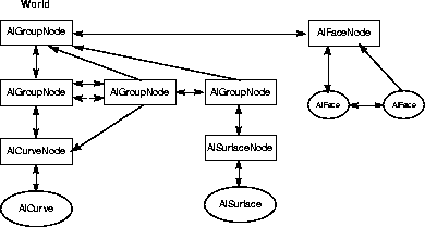
This diagram illustrates an example model. Arrows indicate that a class references the class that it is pointing to. Double sided arrows indictate a two way reference.
The topmost DAG node is called the "world". In this example, the world node (returned by AlUniverse::firstDagNode()) has three group nodes as its "children" and an AlFaceNode as a sibling. Notice that the two group nodes below the topmost DAG node are instances. They both refer to the same curve node. NULL nodes (nothing below them) created in the Alias interactive package are retrieved as AlDagNodes.
There are several classes derived from the DAG node class that refer to specific objects that contain geometry, light, camera or cluster information. (When a DAG node "refers" to an object, it means that the DAG node has the object as a child object.) For instance, a camera node is a DAG node that only refers to a camera object. A light node is a DAG node that only refers to a light object. Combinations such as these tend to be created at the same time, manipulated together, and deleted at the same time. Whenever a DAG node is created, it is inserted into the world position. After creating a DAG node, the method AlUniverse::firstDagNode() will return this node. Please note that it is possible for other creation routines (such as texture creation) to insert nodes into the world position as the first node as well.
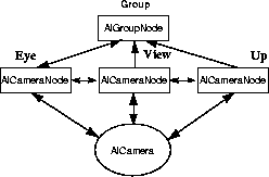
Above, we see three camera nodes and their camera object. The nodes represent the camera's eye, view, and up positions. To create this combination, it would be necessary to instantiate and create an AlOrthographicCamera or an AlPerspectiveCamera. When they are first created, the camera nodes are siblings under an AlGroupNode.
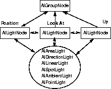
This diagram shows a light and its three light DAG nodes, grouped under a common group node. To create this structure it would be necessary to instantiate and create one of the several different light types. The three light nodes (the position, look at, and up DAG nodes) are created automatically. The three light DAG nodes will be grouped under a common group node. All of the different light types make use of the position DAG node; however, only the AlSpotLight makes use of the look at and up nodes.
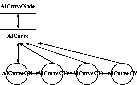
Some objects have child objects as well. For example the AlCurve class has AlCurveCV as a child class.
Here we see a curve DAG node, its curve object, and control vertices (CVs). To create this entire structure, first instantiate and create an AlCurve, then instantiate and create an AlCurveNode object. Note that if an AlCurve is created and not associated with an AlCurveNode, it doesn't become part of the universe. In this case, if the pointer to the AlCurve is lost, the AlCurve becomes wasted memory.
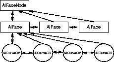
A face is similar to a curve. Here we see a face DAG node, its face objects and their control vertices (CVs). A face must have at least one face object. To create a face, instantiate and create an AlFace then instantiate an AlFaceNode and pass the AlFace to the face node's create method. As with curves, if the pointer to an AlFace is lost without first being associated with an AlFaceNode, the AlFace becomes wasted memory.
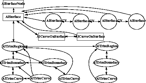
Surfaces like curves have child classes, but surfaces are far more complex and have a far greater number of child classes, including trim classes. There are also surface methods which allow you to project a curve onto the surface, create a curve-on-surface, and other methods which allow you to trim the surface using the curves on the surface.
Above is a surface node, its surface object and associated objects for control vertices (CVs) and curve-on-surface's. To create a surface/surface node pair, first instantiate and create an AlSurface, then instantiate and create a surface node. The surface CVs are created automatically. To create a curve-on-surface, instantiate and set the data of an AlCurveOnSurface object, then add it to an AlSurface. While you are able to add rows of CVs you are not able to delete CVs. Make sure you create a surface node for each surface that you create; a surface without a surface node is not added to the universe, and if the pointer is lost, the surface would become wasted memory.
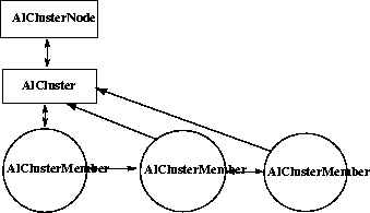
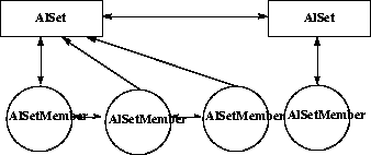
Some objects rather than having a child object, refer to other objects in the universe. In particular the AlSetMember and AlClusterMember classes refer to objects which are components of the set or cluster respectively.
Here we have a cluster DAG node, its cluster object and cluster members. To create this structure, instantiate and create an AlCluster object. It is not possible to create or delete individual AlClusterMember objects. Instead, they are created or deleted when objects are added to or removed from the cluster.
This diagram shows some sets and their set members. A set has no DAG node and is not in the DAG; to get the global list of sets, use the AlUniverse::firstSet() method. To create a set, instantiate and create an AlSet and add members to the set. As with cluster members it is not possible to create or delete individual AlSetMember objects instead, they are created when objects are added to or removed from the set.
Animation and rendering information can also be accessed through the universe. For example, the list of all the channels, actions or shaders in the universe can be traversed. However, this information is also accessible through the objects that use this information. For example, surfaces and faces will have access to the list of shaders and animated objects they use - for example, a CV, light or texture will have access to the channels that animate it. The diagrams below show an animation and rendering example respectively of the relationship between objects that refer to each other. In these figures, all objects are represented in a rectangular box.
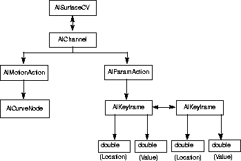
This diagram shows a CV on a surface animated by a motion path and timing curve. To create this structure, instantiate and create an AlMotionAction using an AlCurveNode above the desired motion path curve; instantiate and create an AlChannel with the AlSurfaceCV to animate, the X, Y, or Z parameter of the CV to animate, and the newly-created AlMotionAction; now use the applyWarp() method of the AlChannel, which will create the AlParamAction as a timing curve. Access the two AlKeyframes through the AlParamAction, and change the timing of the animation by using the setLocation() method of AlKeyframe.
 Shaders and Textures
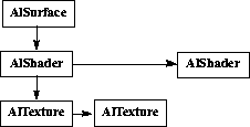
This diagram shows a surface with two shaders, the first shader having two textures. To create this structure, first create a surface. Then create the two shaders with AlShader::create(). To one of them add textures with AlShader::addTexture() and then add the shaders to the surface with AlSurface::assignShader() for the first one and AlSurface::layerShader() for the second one.