The October 2008 issue of Nuts and
Volts Magazine has
an article, by Tom
Fox, titled "Build a Smart Controller
For Your Room Air Conditioner." This controller, which was
jointly designed and tested by Tom Fox and Matthew Fox, uses two
Picaxe microncontrollers. While the original purpose of the
controller was to make possible a walk-in cooler using an inexpensive
room air conditioner, (also see www.magiclandfarms.com)
,
considerable effort was placed in designing it to make it useful in a
wide variety of applications. For instance, it can be used
as a sophisticated thermostat which adjusts the building's
temperature taking into account the present building's temperature AND the
outside temperature! This feature not only will
optimize
the comfort but can save energy.. Another possibility for this
project is as a digital readout anemometer that uses no moving parts!
The only required modifications to the Smart A/C controller to make
these two widely different projects is the PICAXE's program. Many
other diverse applications are possible.
In order to write a PICAXE program you will
require
a PICAXE Programming Editor from Revolution Education, Inc. The
latest version of this software is available as a download, free of
charge, from the PICAXE website at www.PICAXE.co.uk
. This editor is quite sophisticated and easy to use.
However, it has a few problems. One problem is that it
seems to keep open several files at once. You must be real
careful when asked if you want to save the current file. You
might just save an old file over a new one and lose all your session's
work!
To view the the source code, in WORD format, click either PICAXE
28X1 or PICAXE
8M .
Smart A/C Controller update 10/04/2008: First off, the boards I ordered from
ExpressPCB came sooner than they said so I now have a good supply on
hand. The original room air
conditioner I used was an old unit with non-electronic controls.
I used a power relay to directly control the A/C's
compressor. (I could have used a light bulb put next to the controls,
but I didn't) I decided to purchase a new unit (a Haier 8000BTU job
from Walmart) that has digital controls. Since it was brand new I
hesitated in rewiring it so I located the electronic temperature
sensor, and taped two 2700 ohm 1/4W resistors to it. I then
connected the resistors in parallel. These parallel resistors
were then connected in series with J3 (the Smart controller's
compressor relay ) and a 24VAC source. When the Smart controller
calls for cooling, the resistors heat up the sensor and fools the A/C
into thinking the room temperature is above the temperature setting,
which is limited, by the manufacturer, to a minimum temperature of 61F.
Because of the built-in time delay as well as the A/C own built-in
compressor safety features, I recommend setting the
controller's delay to 3 minutes--5 minutes is the default
setting. So far, the cooler has been working like a charm.
I have operated it as low as 38F without problems. Of course, the
cooler will only get this cool if the A/C can keep the room cool enough
when the compressor is operated nearly continously. This means
the A/C must be large enough for the room insulation/size and the
outside temperature can't be extreme. When it gets over 90F out I
have a problem keeping the 60 square foot (470 cubic feet) room cooler
than 55F average temperature. With the temp in the low 70s it can
be kept as cool as a regular fridge. Additional insulation will
no doubt help here and we are presently modifying the size and
insulation of the cooler. No external fan is used since the built-in
fan seems powerful enough. I placed the air flow sensor on the
air intake. It seems a setting of around 18-20 is optimum for the
air flow shutoff--typically I get a reading of 14 (7 deg F difference)
when there is no icing taking place.
One other note. The temperature on the prototype of the Smart A/C
controller appears to be within 1 F (maybe perfect) of the actual
temperature, even though the prototype's power supply puts out 5.05
volts, and not 5.12V. If you use the adjustrable power supply you
might want to tweak things a bit if the displayed temperature differs
more than 1F from the actual temperature. Caution here: make sure
the Smart job's sensor is located out of the case. It gets a
couple of degrees warmer in the case than it does in the room.
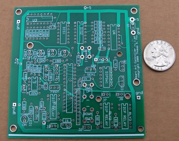
NOW SHIPPING! NOW SHIPPING! NOW SHIPPING! NOW SHIPPING! NOW SHIPPING! Prices are shown below photo:
Main Picaxe Smart A/C Controller
Bare Board --
$12.00
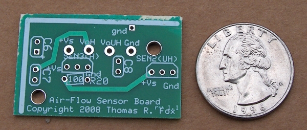
Air Flow Sensor Bare Board --
$4.00
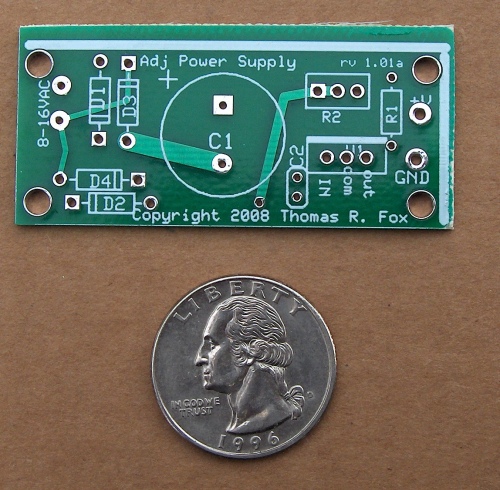
Adjustable Power Supply Bare
Board --
$4.00
(used in both the ILTF and Smart A/C Controller projects)
Note: These boards we sell are
double
sided-boards with plated
through holes, and withsolder masking and
silk-screening! The boards shown in the photos in Nuts and
Volts are prototype boards without
solder masking and silk screening!
NOW SHIPPING! NOW SHIPPING! NOW SHIPPING! NOW SHIPPING! NOW SHIPPING!
Also available are the LM34DZ temperature sensors for $2.00 each.
Shipping Charge: $4.80 via Priority (2-3 day) USPS
----FREE
SHIPPING FOR ORDERS OVER $25!!--- You can order the boards using
PayPal or, send a check. See our Ordering Help page for more information.