|
|
|
Presents: |
|
|
|
Introduction to Automation |
Relays |
|
|
A relay is an electromagnetic switch. Its construction allows low-voltage signal to control or switch on and off high-voltage and/or high-current power that in turn may be used to power electric motors, electric ovens, or other high-power consuming equipment. Relays are also used to provide electrical isolation from one voltage level to another. Control relays are also used to implement logical control functions. |
|

Introduction
Modern automobiles may have as many as a dozen or more relays controlling various high-current loads such as headlights, windshield wiper motors, rear window defrosters, etc. The switch (contact) is opened or closed by energizing or de-energizing the control relay coil (electromagnet). Depending on relay construction, control relay coils may be energized by AC only, DC only or may be energized by either power source. The voltage source applied to the contacts may also be either DC or AC depending on the type of load that must be controlled. Therefore, when selecting a control relay for a particular application, the coil of the relay must be compatible with both the type (DC or AC) and the magnitude (voltage level) of the power supply. The relay contacts should be capable of handling the current and voltage requirements of the load being controlled. Relay contacts are normally either rated according to the wattage or horsepower (for motors relays) of the device that is to be operated. Control relay contacts may be Normally Open (NO), or Normally Closed (NC), or both (SPDT). Some relays have several sets of contacts. In this particular instance, the word set includes a common connection, an open contact, and a closed contact.
Connections
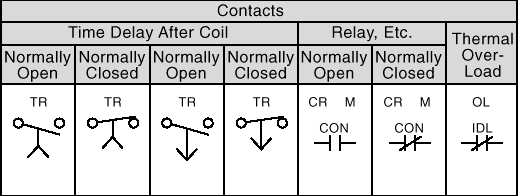
Before wiring any piece of electrical or electronic equipment, it is a good idea to become familiar with all of the connections and the purpose of each. Figures 1a) and b) show the schematic symbols for the coil and contacts of a typical control relay. Figure 1a) shows the ladder diagram representation for a control relay coil and contacts. Figure 1b) shows typical schematic representations for the relay coil and contacts (switches); however, the symbol on the left is most often used in automation. Figure 1 also shows the common connection and normally-open and normally-closed contacts for a relay with three sets of contacts.

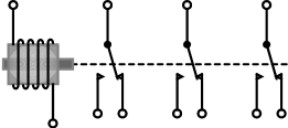
a) b)
Figure 1 Schematic Symbol for a Control Relay
RELAYS
A relay is an electromechanical device that consists of a fixed coil that moves a set of contacts that make or break the path for the electric current. Figure 2 shows examples of typical relays.
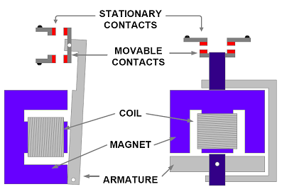
Figure 2 Typical Control Relay Construction
When power is applied to the coil, the armature is attracted towards the coil and the contacts close, allowing current to flow. When the power is removed from the coil, a spring (or gravity) moves the armature away from the coil and the contacts open. Many mechanical arrangements are available to operate the relay contacts, the choice being determined by the current the contacts must carry, the voltage they are expected to handle safely, speed of operation, size constraints, mounting position, the operating life of the relay, and cost.
Relay contacts come in two types: normally open (NO) and normally closed (NC). The word normally applies to the state of the contacts when no power is applied to the relay coil. Thus, when no power is applied to the relay coil, the NO contact is open and the NC contact is closed. Once power is applied to the relay coil, the NO contact closes and the NC contact opens. The figure shows the symbols used for the relay coil and its contacts. Relays can have both NO and NC contacts, in varying quantities from one to 16.
The inflexibility of fixed relays is reduced in three ways: over-design, convertible contacts, and modular relays. It was standard practice to install relays with an assortment of contacts so that many future changes could be accommodated. To some extent, this also reduced the number of relays that had to be stocked. Over-design makes control panels larger and more expensive than needed. Convertible contacts allowed the installer to change from NO to NC or vice versa. This reduced even further the number of items to be stocked, as well as the space required for them. The final improvement was modular relays that could be expanded from two to 12 poles, as required, using standard modules, the user could build them up as needed for the application. Space still had to be left for expansion, however, and the modular relays were more expensive that the fixed ones.

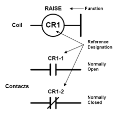
Figure 3 Typical Control Relay
Reference designation
The reference designation used for relays is usually CR (Control Relay). The coil would be referenced as CR1, CR5, etc. the associated contacts would then be CR1-1, CR5-4, etc.
Latching relays
In standard relays the contacts remain closed for NO contacts, and open for NC contacts as long as the coil voltage remains on. Removing the coil voltage causes the coil to release the contacts. Latching relays, which feature a closing coil that operates to energize the relay, are also available. When voltage is removed, the relay's contacts remain in the last position. A separate coil is provided to return the relay back to the opposite position.
Timers
There are two types of timers:
1. On-Delay Timer &
2. Off-Delay Timer
On-Delay Timers will wait a fixed period of time after the timer is energized before changing the position of the contacts.
Off-Delay Timers will change the position of their contacts when energized, then remain in this state for a fixed period of time, then return to their normal state.

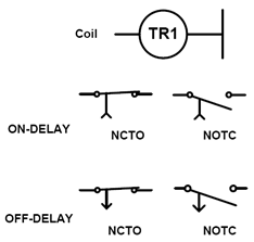
Figure 4 Typical Timer Control Relay
Typical Applications
On/Off Control:
Using a relay and push-button, construct the circuit shown in Figure 5-a).
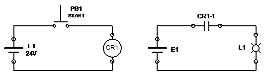
a) b)
Figure 5 Control relay coil circuit and Lamp wired in series with a normally-open contact
Do not yet wire the circuit shown in Figure 5-b). It is always best to build circuits in stages and test each stage separately.
Turn on the power supply (E1), and adjust the voltage to +24 volts, or the specified coil voltage of the relay.
Test the circuit of Figure 5-a) by closing Push-button PB1. If the circuit was wired correctly, you should heard a click or visually observe that the relay’s armature and contacts moved toward the coil.
Turn off power supply El.
Wire the circuit shown in Figure 5-b). In automation, we most often use ladder diagrams to show electrical connections instead of schematics. Figure 6 shows the same circuit in ladder diagram representation.

Figure 6 Ladder diagram representation
Turn on power supply E1.
Push-button PB1. The relay shoud activate, and in turn turn on L1
Turn off power supply El.
Reconnect the circuit according to Figure 6, using the NC contact.
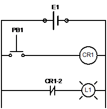
Figure 6 Lamp wired in series with a normally-closed contact
Turn on the power supply E1. The light L1 should turn on.
Puch button PBl. This time the light L1 should turn off.
Note that the circuit implements the logical NOT function.
Turn off power supply E1
The Holding-Relay Circuit
Take a moment to think about all of the electrical and electronic devices you have operated that turn on or start with the touch of a button. For example, many cars have rear-window defoggers or defrosters. By merely pressing and releasing the appropriate button, the window defogger will turn on and stay on for a certain length of time then turn off. The operation of this particular circuit involves several principles. In this part of the experiment, you will have the opportunity to study one of those principles-the holding relay circuit. If you have already studied flip-flops and latches in a digital electronics course, you may recall that these devices will change state (high to low or low to high) when supplied with a momentary pulse or clock input. The holding relay circuit that you will build exhibits a similar operational characteristic. In the case of the holding-relay circuit, you will press and release a push button switch, which will in turn cause your relay to be energized and stay energized or latched in place. This type of circuit is widely used in start-stop circuits that control industrial machinery such as AC motors. In many of these applications, magnetic contactors are used instead of control relays. A magnetic contactor is a high-powered control relay. See section 3 of the theory part of this manual.
Procedure:
With your power supplies turned off, construct the circuits shown in Figure 7.

Figure 7 Latching or Holding relay circuit with L1 connected through a normally open contact
Turn on the power supply. Press and release push button PB2. This is the start push-button. Explain in you logbook why you did not have to hold down PB2 to keep the light On.
Press and release push button switch PBl. This is the stop switch push-button. Explain why you did not have to hold down PBl to keep the light Off.
Turn off power, and modify the circuit to that shown in Figure 8.
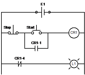
Figure 8 Latching relay circuit with L1 connected through a normally closed contact
Turn on the power supplies. Press and release switch PB2. Describe what happened.
Press and release switch PBl. Describe what happened
Turn off power. The coil in your relay is an inductor. As you may have already studied, inductors resist a change in current. As a result, when the coil in any of the preceding circuits is turned off, there is an inductive kick associated with the collapsing magnetic field around the coil. To minimize damage or pitting of the switch contacts that are in series with the coil, manufacturers of DC powered relays will install a diode or a resistor (this is an ISO standard for automotive relays) in parallel with the coil.
Hysteresis
Your control relay, like some other electronic devices and circuits you will study, exhibits the property of hysteresis. Devices that exhibit hysteresis turn on at one voltage level and turn off at another. The 74LS14 Schmitt-trigger inverter is a digital device that exhibits this property. In this part of the experiment, you will make current measurements demonstrating that the relay you are using also exhibits a hysteresis characteristic.
Procedure:
With your power supply turned off and set for 0 volts, construct the circuit shown in Figure 9.
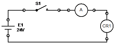
Figure 9 Circuit to measure control relay Pull-in and Drop-out currents
Turn on the power supply, and slowly increase the voltage, while monitoring the current, until the relay just turns on (relay’s armature comes into contact with the coil). Record the value of the current when the relay just turned on. This is referred to as the Pull-in current.
Slowly decrease the power supply voltage (again monitor the current) until the relay just turns off. Record the value of the current when the relay just turns off. This is referred to as the Drop-out current.
Note that the Pull-in current is higher than the Drop-out current.
Manufacturer’s Ratings
Refer to your relay, a data manual and/or the net for the following information.
If the rated coil resistance is not available, you may measure the coil resistance by using an ohmmeter.
|
Relay Manufacturer |
|
|
Coil Voltage Rating |
|
|
Contact Rating(s) |
|
|
Relay Type (DC or AC) |
|
|
Number of Contacts |
|
|
Coil Resistance |
|
|
Duty Rating (continuous or intermittent) |
|
The duty cycle or duty rating of relays, solenoids, or magnetic contactors is often specified as either intermittent or continuous. A relay, solenoid, or any other magnetic device that is rated for continuous duty may be energized for long periods of time without overheating the coil and the subsequent damage that would otherwise result. Coils that have an intermittent rating, on the other hand, must be energized only for short periods of time, then turned off to allow for cooling. Coils with a continuous duty rating typically have more coils (turns or windings) of higher resistance wire. This results in less current draw and, in turn, less heat. The greater number of turns will still result in sufficient magnetomotive force to pull down the armature of a relay or pull in the plunger of a solenoid. If you are in doubt about a particular device’s duty rating, check your sources of information.