Commodore CBM
3032 – How I fixed a garbage screen problem
This page is intended to help a newbie to fix a Commodore - CBM 3032
(PET 2001-N32) with a garbage or blank screen problem without using an oscilloscope
or sophisticated equipment. But you will need some basic equipment, maybe an
eprom programmer, some spare parts and a lot of patience and free time!
Note: this guide can help you also with other model, like 4032, 8032, etc.
but you need to remember those models have a CRTC (CRT Controller) chip and
usually they don’t show the garbage screen when faulty. You will probably start
with a black screen, instead.
In 2001 a
friend donated me a CBM 3032; it was in a garage and I don’t know how many
years it lied in the cold and moisture. When I went back at home and switched
it on, I 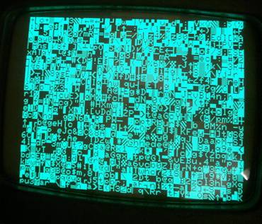 discovered it didn’t work. Such as
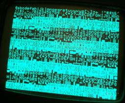
many PET users, I experimented the notorious “garbage screen” problem:
discovered it didn’t work. Such as
many PET users, I experimented the notorious “garbage screen” problem:
Many years
later I discovered this is a normal boot phase: but normally you don’t see it
because the CRT takes few seconds to warm up and start to work. In the
meanwhile the boot has ended, so what you will see at first will be the “READY”
text and the blinking cursor. If you don’t believe it, simply leave the CRT
warm up for at least 30 seconds, then switch off and rapidly (1/2”) switch on
again the computer. It will appear for a while.
But, then,
why sometimes the computer stucks on the “garbage”
screen? Well, it happens because the CPU isn’t working or something is preventing
it to finish its normal boot procedure. Unfortunately in this case the word
“something” means almost every single component on the board. So how to
proceed?
Well, I could
tell what I did to fix it, but it’s better, for now, if I tell you what you
should do, starting from the less invasive procedure. Remember: these first,
easy steps are as important as a deep, invasive diagnostic, so don’t think they
are a simple “bla-bla-bla” and take them seriously! I
wish to have had somebody telling me that many years ago!
DISCLAMEIR:
that’s the way I did and the way you would do only if you haven’t any specific
skill about electronic devices fixing. I’m not saying that’s the best way to
do: it is quite a shot in the dark you can try if you haven’t oscilloscope, logic
probe, professional equipment and/or if you don’t know how to use them. If you
can’t find any better and straight way to fix it, this page could be useful.
And remember: there’s always a better way!
I’m
also assuming you know how to solder a component and remove a component from a
board without damaging anything. Remember: a damaged board is really hard to
fix!
Some simple rules you should follow carefully (I
mean: you MUST follow carefully!)
Don’t work if
you’re tired or if you run out of ideas. In this case, just sleep, rest, leave
it for tomorrow. Seriously, it’s important! I did bad mistakes due to hurry or
tiredness.
Think twice
before acting. Doing nothing is better than doing something wrong or in a hurry.
Proceed one
step at time and test what you did. I.e. don’t remove more than one socket or
one chip at time, etc.
Try to change
as less as possible. Don’t touch anything you didn’t plan to touch (I.e. don’t change
a chip or solder a pin if it isn’t in your “to do” list). Every change could
mean one more problem.
Try to avoid
“blind fixing”: don’t change or touch anything just because “maybe” it could
work.
Write on a
paper every thing
you do and the result of that: it will be important for you to remember what
you did and what changes it produced. Don’t trust your memory; you will not
remember what chip you changed or what pin you soldered. Write a log about what
you did. It will be very useful!
Before to
remove any chip, mark with a pen or paint the original component; this way at
least you know what IC was changed and what IC is still the original one.
Sometimes new ICs are faulty too, and it’s good can count on the chance to undo
what you did.
Before every
step remove the plug from the wall outlet to be sure you’re not working on a
powered board.
Download the
schematics of your computer from the site www.zimmers.net
(look on Google). CBM 3032 should be under the PET/2001 folder. Study them.
Check all of your components are matching the layout page (in other words you
must to be sure, before starting, that somebody didn’t make a mistake trying to
fix the problem).
Check
also if there are some previous fixing / damages on the board / etc.
Let’s start!
First of all,
you should wash the board. Use hot water, a toothbrush and some kitchen soap (be
sure it’s not too aggressive). Carefully clean with the toothbrush every part
of the board, trying to remove the rosin residues around the solder joints.
Take care not to damage any component or wire on the board. Take your time and
do a good job. Then dry it leaving at sun and/or using a hair dryer. Be sure
it’s completely dry before to power it! It takes a lot of time to dry under ICs
and sockets, so you’re advised!
This is a
“must do” step: it’s easy, not invasive, can lead to good results and just took
half of an hour. I fixed a board simply
washing it: I mean from dead to fully working! Some small piece of solders
shortened some pins, preventing it from boot. Too bad I worked on it for days,
swapping ICs and sockets when maybe the only problem I had could be solved
simply washing it!
Carefully
remove and put back again every socketed IC on the
board. You should pay attention not to bend or to break any pin: most
components are really hard or impossible to find today. If you will break a
pin, you could be in trouble finding a replacement and probably it could be
expensive. Remove them once at time, clean it, put it back in his place, then
test. Write somewhere every step you did and the result (or no result, of
course). Sand the pins if they’re rusty, but remember: if they are rusty, the
socket is rusty too: mark the socket as part to be replaced. Now, switch on the
computer and if it doesn’t work, jump to the next step.
Beware: black screen instead of garbage screen doesn’t
mean things are getting worse (as I believed in the past): instead, it usually
means things are getting better! If you get a black screen, wait 30 seconds for
the CRT to warm up, then switch off and on again reapidly;
if you see the garbage and then a black screen, it means the CPU did a step
ahead and you’re on the right path.
If socketed, try to remove the two 6520: they aren’t needed
for the boot (removing the two PIAs in a working machine you will be able to
see the “COMMODORE BASIC” text and the amount of free memory, but you will have
no cursor. You can’t use the computer without PIAs, but at least you can detect
if they’re defective).
Check the
voltage: look at the power supply schematics to understand where to check them.
You should have a +12v, +5v and -5v. If voltage is very different, you will
need to check the power supply section: diodes, ICs and capacitors. Capacitor,
especially the electrolytic ones, tend to degrade and stop to work along many years.
Since you
haven’t neither a logic probe nor an oscilloscope, what you can do is to check the
continuity for every pin of every socketed IC, at
least. Do it in this way (you will need a multimeter):
-
Set the multimeter on “ohm” (or diode
check), then put one probe on the pin “1” and with the other probe try to reach
the solder point under the socket. You should read a continuity (zero ohm). It’s
important the probe is on the pin of the IC and not on the socket contact; this
way you will check both the continuity between the IC and the socket AND the
solder joint.
-
If it seems all ok, check that there
is no continuity among IC pins (of course sometimes continuity is required: in
other words, some adjacent pins are soldered together; see schematics and the pcb). You should check close pins (i.e. 1 and 2, 2 and 3)
but it’s very, very important you also check pins in front of the one you’re
checking: in example, if you’re checking a ROM chip (24 pins), you should check
pin 1 with pins 24 and 23, pin 2 with pins 24, 23 and 22, pin 3 with pins 23,
22 and 21, etc. Believe me, I’ve found and fixed two big problems with this
kind of diagnostic. It’s quite annoying, but important. There were two
shortened pins due to some solder that was making contact between a pin and a
trace. Don’t underestimate this check! It’s boring, it’s frustrating, but DO
IT!
-
Check that every pin of every ROM
chip is connected with the same pin of every other ROM except for the pin 20:
those pins should lead to the DM74154 chip – but don’t trust me 100%, please
check the schematics. If you’re in doubt, always check the schematics (or look
at pcb traces).
-
Check the RAM ICs pins are connected
to other RAM ICs, conforming schematics.
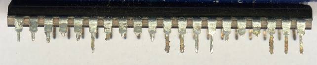
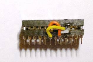
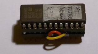
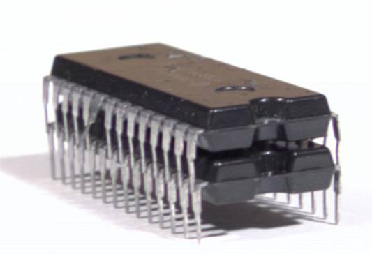
If you will
do this test carefully, you can at least exclude some of the common problems
like interrupted traces or rusty pins and sockets. In my 3032 the original 6522
had very rusty pins: so rusty that they partially disappeared during the years.
See this image of original 6522: the broken pins are pins “eaten” by rust!
If nothing changes, we need to start some invasive tests.
If the computer was expected to work (i.e. it was working when it was stored in
a garage many years ago) then it could have some rusty or simply defective
sockets. I had this problem on the 6502 socket, preventing it to boot. Replace
every socket on the board BUT don’t
replace all at once! Start replacing the 6502 socket.
Remove the original sockets is quite easy using the
following technique, but you need to take great care not to damage the thin
traces on the board! Put a screwdriver under the socket, then rotate it
carefully. The plastic housing will rise while the pins will slowly slide out
from it. Go ahead and remove the plastic housing. Now the pins have been separated
from the housing and it’s easier to remove them individually.
When you removed the socket, take a time to check if
traces under it are ok. I got a problem with a broken trace under a socket:
somebody removed the IC to put the socket, cutting the trace with a
screwdriver. A good way to do this check is to put a strong light behind the
PCB and observe the traces: the light will give a good contrast between the
tracks and the relative transparency of the PCB. Check all of them and clean
the board before to put the new socket. Now solder a fresh one, then check with
an ohmmeter every solder joint you did (in the same way you did when you
checked the other sockets). Remember:
you must to be sure what you did is perfect before to pass over!
A little trick that helped a me a bit: often there’s a
trace between two holes. In some board this trace is painted green, but in my
3032 they weren’t. If too much solder flows through the holes while you’re
soldering the socket, it could happen that some solder flow on the trace, doing
a shortcut. I found useful to paint the trace with a marker in two or three
layers. This way it’s harder for the solder to “jump” on the trace. Of course
it’s better not to use too much solder! Also, using precision sockets gives you
the chance to inspect what you did (see note below).
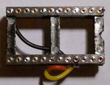
Note: use high precision sockets.
It’s a little harder to put the ICs inside (you need to take great care not to
bend the pins) but they work better and usually it’s easier to inspect their
solder joints. In fact, high precision socket pins have a fat part that doesn’t
fit the board hole, leaving the socket a bit far from the board. This way, you
can simply inspect the solder joints with a strong light behind the board;
checking the solder joints with the ohmmeter is not so critical in this case
because you can see if there are some shortened pins.
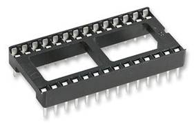
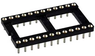
A normal, cheap socket (left) and an
high precision one (right).
Now put the CPU and check the board. When you do this
test you need a working 6502 or a way to test the original one, like using
another computer - i.e. a Commodore Vic-20 or another PET. This is true for
every chip you will replace: you must to be absolutely sure you’re using
working ICs.
See if something changes. The monitor is black, now?
Nothing happens? Good, wait for 30”, switch the computer off and–after a
second- switch it on again. Garbage screen for a while, then black screen?
Great, the CPU is working and is trying to boot but it hangs somewhere.
Still garbage screen? Then do the same thing with the
other sockets.
Note: in my experience, an
apparently good socket doesn’t mean it’s really good. Those old, cheap sockets
fail to work more than you can imagine. Don’t trust them. Replace them all!
If you didn’t solve yet, you will need an EPROM
programmer and an EPROM UV eraser. I bought a cheap programmer (35 euro) on
eBay from China, the Genius G540
programmer, and a cheap UV eraser on eBay from China for 11 euro. You must
choose a programmer that programs 2716 and 2732 types, at least!
You will also need some 2716 and 2732 fresh EPROMs
(Take at least three 2716 and seven 2732). On eBay – China and Hong Kong
sellers – usually are quite cheap too. But be sure your programmer can handle
that specific brand and kind! Some brands/kinds couldn’t be supported by a
given programmer.
You will probably need some components too; well, you
could need some backups of almost every components on the board! It includes of
course 2114 video RAM, 4116 RAM chips, 6502, 6520, 6522, and almost every 74xxx
component. If you can’t find them at your local shop, you would take a look on
eBay, usually you will find them there; or, if you have a working VIC-20, you can get some of them from it: 6502, 6522, 2114
Video RAM and few 74xxx logic ICs. In this case, the right thing to do is to
extract once at time of every kind from the VIC (i.e. no need to extract the three 2114 from the VIC: you only need a socketed one to test the PET ICs) and replace it with a
socket. Then, put the original IC you just removed again into the VIC, using
the new socket you put, and test the VIC. Does it work fine? Good, now it’s
time to check the PET IC into the VIC to see if it works or if it’s faulty!
Most 74xxx series IC and sockets can be found at good
price on eBay too. China and Hong Kong vendors normally have cheapest prices
but it could take some time to arrive.
IMO: if you don’t care with waste of money, take some
of the important ICs for future repairs: 6502, 6520, 6522, DM74154, 2114 and
4116 RAM, etc.; actually they’re still available; how to know what will happen
next 20 or 30 years? Many ICs from Commodore are no longer available. There’s a
cheap 6502 clone labeled CM630P. I bought 7 of them, no problem, they seem to
be a fully replacement.
The only chip we can assume (at 99.9%) is working, is
the ROM characters generator (901447-10 in UF10) because you’re seeing a screen
full of chars. But of course it isn’t wise to be 100% sure about anything!
If you have the Eprom programmer, it’s always a good
idea to check every ROM. You can choose between two options, but in my
experience it’s a good idea to try both, just to have a crossing test that will
cover every possible mistake/issue.
First option:
Check if the ROMs are faulty
If your Eprom programmer can’t read 2332 ROMs or 2532
EPROMs (that’s quite probable, since these kinds are very old), you will need
to build an adapter that will make your programmer to read 2332 ROM (PET Kernal
and Basic ROMs) as they were 2732; you need just two 24 pin DIP sockets and two
diodes (1N4148 are ok).
Note: I got
the following info and picture from www.vintage-computer.com
forum: I’m just copying here for your convenience. I checked this project and
it works fine, at least to read the ROMs: it should be ok to program a 2532
EPROM too, in case you have any and you don’t want to use a socket adapter
inside your PET, but I didn’t test it for myself yet.
VERY
IMPORTANT: this adapter is only for 32 k ROMS (Kernal and Basic). Don’t use it
for Chars ROM and Edit ROM, since they’re 16 k and don’t require any adapter
(they’re pin compatible with 2716 eprom).
Look at this picture:
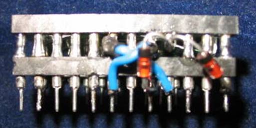
You have an “upper socket” and a “lower socket”.
All the pins are connected together, except for these
pins, that should be connected through wires, this way:
Upper socket Lower
socket
Pin 20 ------- Pin 18
Pin 18 ------- Pin 21
Pin 21 ![]() Pin 24
Pin 24
Pin 21 ![]() Pin 20
Pin 20
You need to cut the pins 18, 20 and 21 on the upper
socket and put something (like some electrical tape, glue, etc.) on the lower
socket to be sure the remaining parts can’t touch the lower pins. I use two or
three layers of paper tape cut in small strips. Then connect the pin 20, upper
socket to the pin 18, lower socket and the pin 18, upper socket to the pin 21,
lower socket, using a thin wire. Be sure not to shortcut adjacent pins while
soldering, and be sure the solder doesn’t flow on the lower socket pins, since
they will need to enter smoothly in the EPROM programmer socket!
You also need to connect the pin 21, upper socket to
pins 20 and 24, lower socket, using two diodes. See above images about how the
diode polarity needs to be oriented: the black band of both diodes must to be
on the upper socket side.
Note: in my
adapter I passed all wires and diodes between the two socket, internally: it
will give to your adapter a better aspect and there are less chances to break a
wire or a diode while you’re handling the socket.
When you’ve done and you’re sure everything is ok, solder
all the other pins together (I mean pin 1 upper socket with pin 1 lower socket,
pin 2 upper socket with pin 2 lower socket, etc.)
Ok, the adapter is ready, now time to check the ROMs!
Take the first original PET ROM, put it into the adapter (be sure it’s
correctly oriented) and put the adapter into the EPROM programmer. Choose a
2732 eprom in the eprom list. I used the ST brand, 2732 model. Note: As told,
if you’re checking Edit ROM or Char ROM, you don’t need the adapter, simply put
the ROM in your Eprom programmer and choose a 2716 eprom from the eprom list.
Go to the page:
http://www.zimmers.net/anonftp/pub/cbm/firmware/computers/pet/index.html
and download the image of the same ROM. Load it as BIN
archive into your programmer. Now choose the “verify” function from the Eprom
programmer software. It will compare the image file you downloaded with the
content inside the ROM. It should tell you something like “Verify ok”. If you
get an error, try the “read” function from the Eprom programmer software. If it
can read (load) the content of the ROM, your ROM could be ok but different from
the image you got from the above site. This is possible especially when you’re
checking the Character generator ROM and the Edit ROM. In this case you can try to swap it with an
EPROM programmed with the image from the site.
Second
option: Try to swap the original ROMs with EPROMs
Go to the page:
http://www.zimmers.net/anonftp/pub/cbm/firmware/computers/pet/index.html
and download the same ROM set of your PET (simply read the code on your ROM
chips and download the same image from the link above). In a CBM 3032 you can
use four different set of ROM chips: two are for graphic keyboard and two for
business keyboard. The 3032 has the graphic keyboard, but for diagnostic
purposes you should check all of them. In my case, the Basic 2 – business keyboard set worked, the Basic 2 – graphic keyboard set (the original set for this machine)
didn’t work; both Basic 4 sets
worked. I later discovered the trace from 6522 pin #15 to 6520 pin #18 was
interrupted under the 6522 socket (almost impossible to see, I found it using
the multimeter) and it prevented the computer to boot with the BASIC 2 – edit
ROM for graphic keyboard (but worked fine with the other rom
set). Bizarre, isn’t it?
SOCKET BASIC 2 BASIC 4
--------------------
--------------------
UD9 kernal - 901465-03
kernal-
901465-22
UD8
edit-2-e000.901447-24 edit- 4-e000.901447-29 <<graphic
keyboard set
UD7
basic-2-d000.901465-02
basic-4-d000.901465-21 for CBM
3032: you
UD6
basic-2-c000.901465-01
basic-4-c000.901465-20 should
use one of
UD5
basic-4-b000.901465-23 this two
sets
--------------------
--------------------
UD9 kernal -
901465-03 kernal- 901465-22
UD8
edit-2-e000.901474-01 edit- 4-e000.901474-02 <<business
keyboard set
UD7
basic-2-d000.901465-02
basic-4-d000.901465-21 Will
work on 3032 but
UD6
basic-2-c000.901465-01
basic-4-c000.901465-20 the
keyboard mapping
UD5
basic-4-b000.901465-23 will be
wrong.
Note: this is just for 30xx models; for other models
like 40x, 80xx, etc. some differences could be expected. I’m also not sure if
40xx and 80xx models will run with BASIC 2 ROM set.
In first you
should program a 2732 eprom using the petester.bin
image: you can find it in the forum www.vintage-computer.com
or here. Since this
guide cover can be useful also for PET 8032 fixing, here you can find
a Pet Tester image for the 8032 model, thanks to the Vintage Computer forum
gurus! It will produce a garbage on the half,
lower part of the monitor. This is normal since it’s based on the original 40
column petester.bin.
Since 2732
eprom isn’t pin compatible with old Commodore ROMs, you have to make an adapter
using two sockets. In fact some pins of the 2732 must to be connected in
different places. In other words, three 2732
pins must to be connected in different places on the socket: Pin
#20 to pin 12 on the socket, pin #21 to
pin 18 on the socket, pin #18 to the pin 20 on the socket.
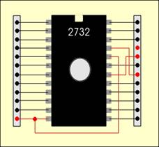
Upper left: electrical scheme. Others: adapter with and without the
EPROM installed.
Put this
adapter with the petester.bin EPROM in the kernal
(socket UD9) and switch on the computer. You can have two behaviors:
A)
Nothing happens (garbage or black
screen).
B)
A screen fully populated by
sequential characters and number that endlessly changes in a page full of “g”,
“b” or mix of “g” and “b” and back on the chars test again. That’s the RAM test
page: “g” means good RAM, “b” means bad RAM.
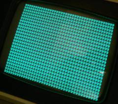
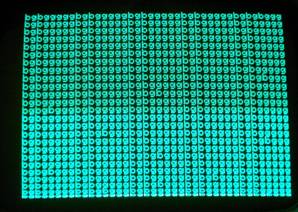
Pet Tester running: char test, ram test
(all “g” - good) and ram test (both “g” – good and “b” – bad)
Of course the
B) option is what we like to see, because it means the CPU is working fine and
a simple diagnostic can be executed. If you have some “g” and some “b” you
should check at first the 4116 chips; possibly one of them is wrong (or many!).
What you can do is to check with your multimeter that all the pins are
correctly soldered (every RAM chip pin is connected with the same pin of some
other RAM chips; see schematics or look at traces to discover who’s who). If
all sounds ok, you can extract every chip and replace with a socket. Then,
check the extracted chip in your VIC-20 and proceed this way until to find the
bad one (if any). Finally, check again with petester.
Note: a test
you can do before to extract every RAM ICs is to “piggyback” them with fresh
ones: just take a fresh 4116 and put it on the other, taking care same pins are
doing a good contact, like shown in the below picture. This way you should able
to check what RAM ICs is working. You can do it with 4116 (that is our purpose
with the petester) and 2114 ICs and often it will
work with many ICs.
Check one
chip at time and see if the diagnostic will change in “g”. If you got more “g”
than before but there are still some “b”, try to leave the piggyback chip and
put another one with the same technique.
Note: with
the piggyback method you can find a bad chip, but if nothing changes will not
an affordable result. In other words, changes will pinpoint in the right
direction, but no changes doesn’t mean the chip you tested is ok; sometimes,
the piggyback doesn’t work, due to lack of contact.
If you don’t
want to extract a bad chip you can solder a good one leaving it piggyback on
the bad one.
Source: internet. – Don’t
bend the pin like showed in this picture!
If you can’t
find 4116 spare chips to buy or you like shortcuts, you have an easy exit: buy
the Nicholas Welte’s RAM/ROM expansion (see: http://vic-20.de/x1541/hardware/petram.html)
that allows you to replace the original RAM and ROM banks with its embedded
ones. When I bought it years ago, Nicholas sent me the expansion fully
assembled with all chipset programmed and ready for PET. You maybe would ask
him to do the same for you. Buy also a pair of RAM and Flash programmed chips
more, just in case!
Ask him to
program for you a Basic 2 and Basic 4 set (graphic keyboard). You can use this expansion also as a good
diagnostic tool to exclude a whole block -ROM and/or RAM- and get focused on
another block. Or you can program your ATMEL flash ROM (AT29C010A) using the
ROM images I prepared and tested on my machines: download here
the zip file containing both 3032 BASIC 2 and 8032 BASIC 4 images.
Disclaimer: I’m not affiliated with Nicholas. I
simply bought his expansion and I used it. It worked fine as RAM and ROM
expansion for me both for 3032 and 8032 machines.
Note: An alternative to the Welte’s project should be the PETvet
(http://www.bitfixer.com/bf/petvet).
I think it’s the same concept in other words, but since I don’t own a PETvet, I can’t say.
You should
also check the other ICs involved, especially (but not only) if you have a page
full of “b”. In my case the 7425 (B2, on the lower-right corner of the board)
was faulty and in normal mode (not petester mode) led to a black screen
issue. Look at schematics page 5: RAM from Zimmers.net / Pet / 2001 what are the
involved chips. Also the four chips 74153 (C10-C13) must to be verified if you
have RAM issues.
Another
problem can be due to the video RAM (2114 ICs). You should check them, too:
piggyback or socket them.
If/when you
have a petester correctly running (page full of “g”), try to put the original
ROM in their sockets. Still nothing? Well, then try to program a full set of
eprom (check all the four set I presented above).
Note: for the edit ROM (D8) you must
use a 2716 eprom. If you have only 2732 ones you must to program one of them
starting at $0800 address. In every case
don’t use 2732-2532 adapter in UD8: plug the EPROM directly on the board
socket. Beware at EPROM polarity! If
you put it reversed (eprom pin 1 in socket pin 21) you will fry your EPROM (you
will see a small flash into your eprom window: believe me, I did it twice!).
Of course all
the ICs can be faulty and most of them can potentially lead to a garbage screen
issue.
Here’s what I did - I’m not saying it was right or wise, but in the end
it paid!
I got my
faulty 3032 in the far 2001; At that time I didn’t find much info on the web
about this problem. The few people that tried to help me, just told me: Check RAM. Check ROM. You need an eprom
programmer. (and they were quite expensive). I had an 8032-SK without keyboard
and some VIC-20, so I had a chance at least to check some components. Since I
felt the ICs were running out of stock on the market, I bought every chip I
found: 6502, 6522, 6520, RAM 4116, etc. So, in the end, I had enough spare
parts to fix it.
Since I
hadn’t (and I haven’t) enough knowledge to proceed in a smart way, I started
with a “brute force attack”: I changed every chip I can, socketing
them (actually *every* chip on the board is socketed).
I changed every 74xxx, PIAs, VIA, CPU, also some electrolytic capacitors.
Nothing worked. I didn’t do that in a single task; to be honest, it took me 12
years. Every few months I took the 3032, worked a bit and got frustrated. I put
it away, again, swearing that I will never do it again. And few months after I
was again on it. For few years it waited in a box in my garage in Italy while I
and my family was teleporting ourselves in Brazil. A couple of years ago the containter with our goods arrived here, so I started again
to suffer on it. And, finally, the evolution: some friends at www.vintage-computer.com and www.6502.org
forums helped me a lot, explaining what I should expect, what I should do, and
what a given behavior stands for. I understood a lot of interesting things I
didn’t know, that led me to find all the issues. This is what I did in the past
two months:
-
Most of the original sockets (from
1979!) were rusty. To be sure, I changed all of them.
-
I found some pins under the option
ROM sockets were shortened.
-
I had a strange behavior that nobody
understood: it worked with both BASIC 2 and BASIC 4 business keyboard romset,
but not with the same romset for graphic keyboard (it
did a black screen). Then, suddenly, after a check I did on some 74xxx ICs, it
suddenly started to work with BASIC 4
graphic keyboard too, but still nothing with BASIC 2 graphic keyboard. As told, I later discovered a trace was
broken and it prevented that given ROM (and only that) to boot.
-
After to get back to life for an
entire evening, it died again (during the night: I switched it off while it was
working fine, and in the morning it wasn’t working yet). I discovered through
the Nicholas Welte’s RAM/ROM expansion that I had a
RAM problem. After a day spent suffering on the board, finally I discovered the
culprit: a faulty 7425 (UB2).
Now it’s
working fine. For now. Past years aside, to get it running took to me and to my
new friends on the forums about 15 days, working eight hours per day or more. I
can’t count how many eprom I programmed and erased, how many chips I changed,
how many sockets I verified with my multimeter. When
we hit in the Basic 2 romset problem, we all had the
feeling we were clutching at straws. I was really lucky to have Mike (“mikeS”), Dave (“Dave_m”) and Jeff
(“DrJefyll”) on my side: they helped me not just
technically; they encouraged me so much that I kept fighting with this haunted
computer until to exorcise it. Because it wasn’t a fixing, it was an exorcism.
I’m sure of it ;-)
Giovi,
30th june, 2013
Some credits (still with BASIC 4 romset: I
didn’t fix the BASIC 2 romset problem yet).
You can send me an e-mail at (remove the “ZZ” from the below address):
|
BrewZZcontrol |
(AT) |
Katamail |
(DOT) com |