|
Main Index Buy LED lights Introduction Walkthroughs Forums  Contributors
Links Guestbook Home Tech Index Version Guide Progress Reviews Submissions LED info News Archive 
|
|
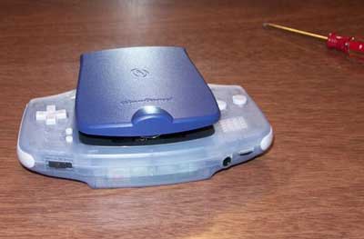
Modding the InterAct/Nyko GlowGuard with Dual White LED's January 12, 2002 by Xcandescent This mod is very similar to the Pelican mod. I don't know anything about electronics, so if I can do it, pretty much anyone with a decent amount of dexterity and sense should be able to. (Of course, I've worked with soldering irons before. If you haven't, you'll definitely want to bone up on soldering basics and practice soldering spare wires before you attempt anything.) On the surface, it might seem weird to want to mod a GlowGuard at all -- seeing as its construction is completely inferior to a Pelican Light Shield Advance (or LSA) -- but there are two very good reasons to try. The first is that the LSA uses the same tri-wing security screws as the GBA -- and most people I know don't own the appropriate bits. The second (and more important) is that Pelican has released three different versions of the LSA. Of those, the LED model is apparently difficult/impossible to get open, the new incandescent model doesn't supply enough voltage to power an LED, and the original is damned hard to track down and identify. In fact, from what I hear, the only way to tell for certain what version you have is to pop it open with a tri-wing screwdriver, and read the version number on the circuit board. The GlowGuard has the advantage of already being able to power an LED (since it comes with a crappy one), and using ordinary Phillips screws instead of weird tri-wing ones. People have pulled off dual-LED mods with the Pelican by putting the LED's in parallel, so the same should be (and is) doable here. Incidentally, Interact doesn't MAKE the GlowGuard -- it's just their brand. If you look on the back of the packaging, Nyko is listed as the manufacturer. This explains a lot of things (like, for example, why it's physically such a piece of crap). Some caveats: No one has actually taken a reading to see how much power is actually being transmitted to the LED. The GlowGuard does not have a dimmer, so it's not clear to me how playing with a normal GB/GBC game might affect it. (I would HOPE that the circuitry does the necessary voltage adjustments, but I have no idea.) Putting two LED's in parallel works, but that's about all I can tell you. I don't know how adding a second LED to the circuit affects power consumption or the life of the LED's themselves. I did a preliminary test with some 1600 mAH AA NiMH batteries I bought, and the GBA with modded GlowGuard went for 6 hours before the low battery light came on. I won't be held responsible for any actions taken while attempting this mod. I can barely be held responsible for my own. ;) REQUIREMENTS
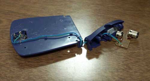
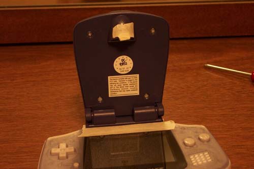
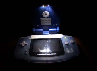
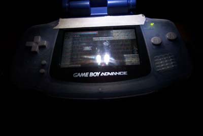
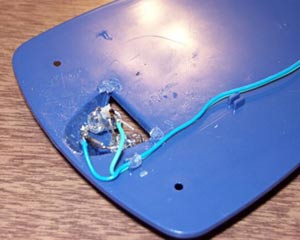
SUMMARY The big problem with mounting two LED's in a GlowGuard is that there's no easy way to secure them. The plastic holder won't work, because it already has a hole in the center, and adding more holes would just tear it to bits (assuming you can even get the original LED out). If you have the equipment (Dremel?), you could try to put two 5mm holes in the plastic lens cover, or trim holes around the sides-- but I didn't have the equipment. (OK, I was stupid enough to buy a drill, but I threw that idea out the window really quick.) One could also try melting the plastic casing and sticking the LED to that. After all, that's what Nyko did to secure the plastic LED holder (I'm NOT kidding!) My solution was to use a quick-drying, clear epoxy to mount the LED's to each side of the semi-circular hole. Epoxy has the property of being a physically thick substance, which means that you can use it to fill in the empty space between the LED's and the plastic casing (which is the #1 obstacle to using adhesive here). Clear epoxy won't block light transmission, should you manage to mess up and cover your LEDs with it (like I did). A fast-drying epoxy should be firm enough within 15-30 minutes to let you get on with the rest of the mod. Once you have the LED's glued in place (and hopefully aimed properly), everything else is cake. Just solder in the power wires, plug the GlowGuard in to make sure the circuit works, then put the whole thing back together. Now for the procedure: STEP 1 Look at the base of your GlowGuard. Notice the plastic buttons on the side that you press to mount it to your GBA. THOSE ARE LOOSE PARTS! You need to be careful that they don't fly off and get lost when you remove the base. Remove the three screws from the (mounting) base of the GlowGuard with your Phillips #0 screwdriver. Once screws are removed, use your fingers to hold the base closed, then position it so the base is sitting in your hand, screw holes down. Lift the GlowGuard away from the base; if you do this right, all the loose parts should stay in the base, and not fly out all over the room. Set base and screws aside in a safe place. STEP 2 Remove the two long screws holding the circuit board. The heads of these screws were incredibly soft on mine, so you may need to push down hard while unscrewing to avoid screwing up the heads. Set screws aside, and remove the circuit board. Make sure the attached power wire is nice and loose. STEP 3 Pop the hinge between the base and the cover, on the side closest to the link port that plugs INTO the GBA. You can only do it on that side, because the other side has a piece of solid plastic which functions as a locking mechanism. Notice how the power wire actually goes through the hollow hinge joint. Also notice the piece of plastic on the other side with the rectangular protrusion -- yep, that's the "clicking" mechanism. If you're good enough, you could probably file the rectangular part away and surround the remaining axle with rubber, so that the hinge moves smoothly but is still held in place with friction. I had no rubber seals around to try with it, so I didn't bother. STEP 4 Remove the 4 screws on the underside of the (large) cover. Notice that the two pieces of the cover are still being held together. If you examine the hinge area, you'll notice that there's a good hunk of plastic on both sides holding it in. Because this is part of the hinge, you can't afford to break it. On the side which doesn't have the power wire running out of it, insert your metal pry tool (or thin screwdriver) into the hinge hole, and pull the plastic towards you, and away from the other piece of the cover. Work the plastic outwards until you are able to physically pry that side of the cover off. Once that's done, you can separate the two pieces of the cover easily. STEP 5 Examine the piece of plastic holding the current LED. Notice how it's MELTED into place. Take whatever sharp implements you have on hand (screwdriver, razor, etc.), and scrape off melted plastic until the plastic mount comes loose. Pop out the clear plastic lens and discard. STEP 6 Heat up your soldering iron. (Mine is 25 watts, and takes 15 mins. Of course, some irons heat up a lot faster.) Melt the solder connecting the power wires to the original LED, and use your desoldering tool to suck out the melted flux. Try to get the wires as clear of solder as you can (desoldering tape might help). Toss out the plastic mount and LED. STEP 7 Turn your soldering iron off; you won't need it again for a while. Plug the circuit board back into your GBA, put in a Game Boy *ADVANCE* game, and turn you GBA on to power the wires. Take out your 2 new LED's, and determine their proper polarity by touching the wires to them. If they light up, you got it right; if they don't light up, switch wires. Once you've determined the proper polarity for each LED, write it down somewhere. Turn off your GBA and unplug the GlowGuard from it. The circuit board in the GlowGuard designates the green wire as Negative, and the blue wire as Positive. The Radio Shack LED's feature two wires of differing lengths; the shorter one should be Negative, but you'll want to double check this. STEP 8 We're going to mount the LED's, but without pictures this is hard to explain. I'll try to take more pictures the next time I do this mod. The LED's are gonna get glued to the sides of the semi-circular aperture where the original LED used to be. The negative wires on each LED will then get trimmed and soldered together; then the positive wires. You CANNOT cross the positive wires with the negative ones -- which means that you have to orient the LED's so that, when you bend the wires down to solder them, the positive and negative wires become parallel to each other. Easiest way to do this is to orient the LED's with one wire above the other -- but with the same polarity on the top for both. (Either negative above positive, or positive above negative.) Mix together the epoxy, let it sit for a couple of minutes, then apply it to the sides of the semi-circular aperture. Orient the LED's as described above, and hold them to the epoxy. Try to aim the LED's straight through the opening. Hold the LED's in place until the epoxy sets, then wait for the epoxy to dry to a "workable" condition -- whatever amount of time is specified in the epoxy's directions. (For me, it was 15 minutes.) STEP 9 (optional) If you wish, you can try to strip a bit of the insulator off the power leads to give yourself more room to solder. I was unable to do this with a normal wire stripper, but I suspect a razor blade might work. In any case, it is possible to attach the power leads without stripping any additional insulation, so I leave it up to you. STEP 10 Warm up your soldering iron again. Use your wire cutter to trim down the LED wires as necessary, then bend them over each other. Remember that you need to be able to put the cover back on, so figure out how much room you have to work with and make the bends accordingly. The negative and positive leads should be parallel (not touching). STEP 11 Tin your soldering iron. Solder the positive LED leads together. Solder the negative LED leads together. Do NOT solder positive to negative, or vice versa. ;) STEP 12 Solder the positive power lead to the positive LED leads. Solder the negative power lead to the negative LED leads. The power leads don't stay in place very easily, so you may have trouble holding one down while simultaneously holding a roll of solder and manipulating the iron with the other hand. Tucking the power lead under the wire you want to solder it to sometimes helps, as does cutting off a short piece of solder to work with (though I'm not a big fan of skin contact with lead). So does stripping away more insulation, since that gives you more room to work with. STEP 13 (optional) If you've done this right, the length of exposed wiring should be really short -- and the leads on the Radio Shack LED's are firm enough that they shouldn't move. (The strength of the soldered joint also helps with this.) However, you're welcome to wrap any exposed wiring in electrical tape if you're so inclined. STEP 14 Plug the GlowGuard circuit board into your GBA, put in a GBA game, and turn it on. If your LED's light up, congratulations! If they don't, check your connections; you may need to re-solder. STEP 15 Once you're satisfied that the LED's work, turn off the GBA and unplug the GlowGuard from it. Start reassembling the GlowGuard by putting the two pieces of the cover back together, snapping everything firmly into place. Reattach the four short screws to the cover. STEP 16 This is where it gets ugly. If you examined the wiring around the hinge joint closely when you first disassembled the GlowGuard, you may have noticed that the insulation seems awfully bent and thin around that area. You're about to find out why. Slide the plastic spacer disk along the wire until it hits plastic on either end. (Doesn't matter which.) Insert the plastic axle on the opposite side into the hinge hole on the cover. Lower the cover into the hinge on the wire side -- pulling loose wire out of the way by yanking on the circuit board side. Eventually, you'll get to a point where the hinge will almost be back in place, but there's a teeny bit of wire in the way. If you examine how the hinge is constructed, you'll find that this is BY DESIGN, and the only way around it is to yank hard on the wire while shoving the cover back into the hinge. This is why the wire is thin and frayed. This is also why I'm never disassembling my modded GlowGuard again, even for pictures. STEP 17 Assuming you don't flat out break it, gather all the loose wire and tuck it into the space under the circuit board. Remount the circuit board using the two long screws. STEP 18 Put the two pieces of the base back together, making sure not to drop any loose pieces. Use the 3 remaining screws to secure it in place. STEP 19 Plug your GlowGuard into your GBA, and turn it on. If it works, you're done! If not ... well, a replacement GlowGuard and LED's should only run $20, right? ;) I've submitted pictures of my mod to the site; hopefully they'll be posted with this article. One of the pictures shows a folded over piece of masking tape stuck to the very end of the light aperture. That's a makeshift "cushion" to prevent screen scratching (did I mention the GlowGuard is a poorly constructed piece of crap?) Pelican LSA's have a thin foam strip which does the same thing; feel free to improvise. You'll also notice that I applied a piece of masking tape to the top of my GBA. Black electrical tape is pretty darned reflective, so I didn't understand why anyone would use that to reduce glare. I substituted masking tape instead. Hopefully someone will find a better solution for reducing screen glare, though from what I understand the prospects aren't good until the frontlight kit comes out (because it's a REFLECTIVE screen ... so light has to pass through both ways, hence glare. Once a frontlight is in place, you can polarize the screen to only let out light.) Speaking of which ... anyone know where I can get some decent tri-wing security bits? =) Picture section
|