Created : 4 november 2001
Last updated : 12 april 2002
Classification : Construction analysis
Copyright : restricted shareware
Status : Being constructed, Grammer check needed.
Comments : Adviced to be used in conjunction with genaker document, see link under "Related links"
This particular page looks at mast setups and we refer to the complete genaker document (Word 97) for the building of your own COMPLETE genaker setup.
All the setups presented on this page allow simple switching between short and long luffed genakers as might be used in the F16 HP weight equalization system. Ofcourse this system is not operational at this time and will only be made operational if inequality between crews of different weights can be proven.
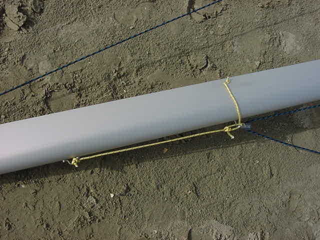
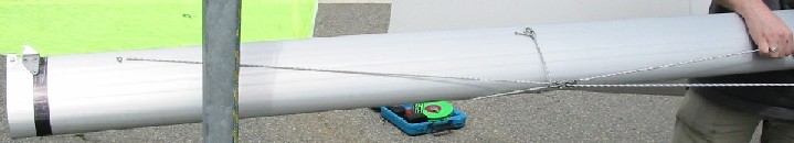
All presented setups are fixed using knotted pieces of high strength line with a tough outer mantel and blind rivest (Stainless steel, Monel, but not aluminium ones). The lines are either tied of to eyestraps riveted to the mast or tied of to the masttrack. The last by running the line though a drilled hole on the masttrack and placing a small (overhand) knot on the other side. You can nearly completely eliminate wear by smoothing the edges of the drilled holes by shortly "post-drilling" them with a much larger diameter drill.
See picture below for the general idea.
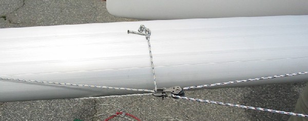
The most simple and cost effective methode. The investment is only about 1 mtr. of high strength and though Dyneema line and a normal single pully block for up to 10 mm diameter line.
The force vector diagram is as follows :
Multiple tie off solution can be dreamed of. Toname a few : sliding Fishers hitch (often used in powerkiting), two small loops in the line where the shackle is attached too, etc.
The loop line must be very close to the mast so they shouldn't be made to long.
Only real disadvantage of this methode is that the Turtle block requires drilling two holes for the blind rivet or bolts that could potentially be leak in a sealed mastsection. Methode 1 can be made to avoid this. Methode 4 is an example of how to achieve this
The vector diagram is abit more complex and it is clearly visible that the position of the ring (which is measured for the max. gate height) is somewhat dynamic.
This setup works and I have used it personally for the last two seasons. Sadly I have no picture of it yet.
Disadvantages :
-1- The genaker will interfere with mastrotation and try to under rotate the mast
-2- When the mast is forcefully rotated the eyestrap experiences high sideways loads, very possibly damaging the mast and rivets
-3- You have no less than 4 potential leaks at a high point on the mast on a preferably sealed mast.
The force vector diagram is as follows :
This methode has an extra advantage for carbon mast owners.
The extra advantages :
- Absolutely no added holes in your sealed part of mast.
- The block makes the most horizontal movement next to a all steel bail hound
- BEST : It tried to underrotate the mast the least next to the all steel bail hound
- It is also the cheapest hound possible
- By far most of the load is transmitted just through the vertical line which can be tied of the the mainsail hook which take such loads easily. Horinzontal loop is hardly loaded up. Great for carbon masts
The force vector diagram is as follows :
- You drill through the masttrack to the other side and make the knot on the outside of the mast
- You round of the edges of the hole using a larger diameter drill
- keep the horinzontal loop as short as possible = close to the mast
- Use a round legged shackle without sharp angles or parts.
F loop = 38 % * luff genaker
F loop = 38 % * luff genaker
F loop = 0-3 % * luff genaker
F loop = 2-5 % * luff genaker
F loop = 38 % * luff genaker
F loop = 38 % * luff genaker
Don�t get fooled by the appearence of the drawings. All methodes produce the same bending moments and axial loads in the mast section when the genaker hoists (tang) heights are the same. These loads are fully independend of the tang methode used. The methodes presented only differ in the creation of (local) point loads. The last is important for the construction of the setup given a particular gate height, the first wether to fit a genaker (at that given gate height) at all.
All methodes can be quickly adjusted to a different hoist heights by replacing the ring by a shackle and fixing the shackle to the other tang line. Only the methodes with a upline need to device a way of adjusting the length of this line. In the single upline methode the line can be adjusted easily by using an end knot+loop and a knot somewhere halveway the line and sliding up an down a fishers hitch.