DIY the UP-06MOD of TANAKA
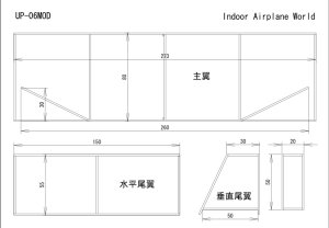
DOWNLOAD THE PLAN
Read the notice of Tanaka
(in English, translated from Japanese by Babelfish)
DOWNLOAD THE PLAN
Read the notice of Tanaka
(in English, translated from Japanese by Babelfish)
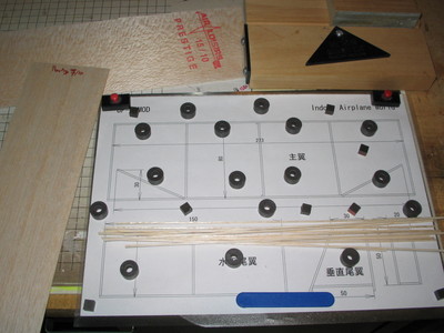
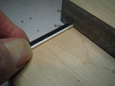
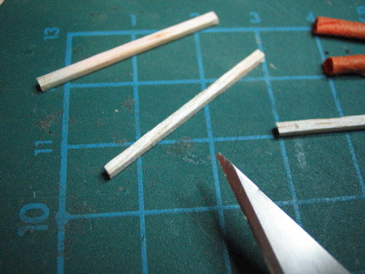
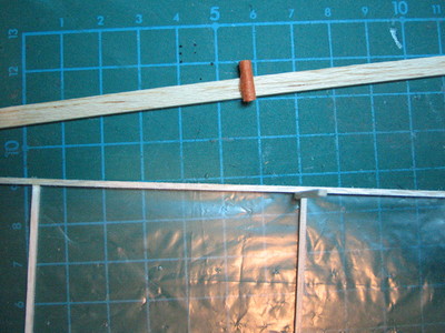
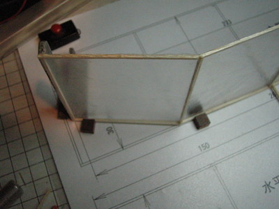
Here is the workstation from a balsa wood of 15/10 on size rods 1.5 x1, 5mm, magnets ensure the continuance. It can cut balsa sticks with a stripper or better with "stripper Jim JONES"at Peck Polymers (but more expensive!): :
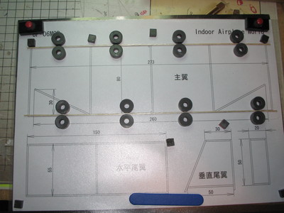
It has the leading edge and trailing edge (chopsticks: 1.5 x1, 5), the magnets keep parts:
The profile is flat, you cut the ribs in the same chopsticks:
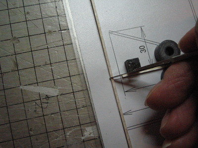
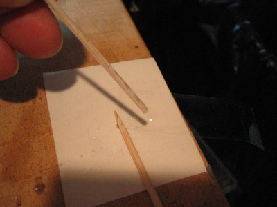
The end of each rib is sanded :
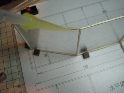
Just put a drop of of CA on the rib:
Three ribs are glued and always maintained by magnets:
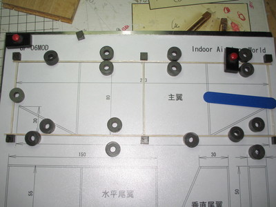
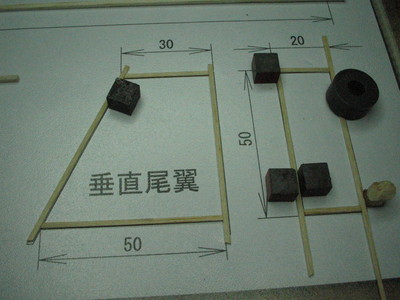
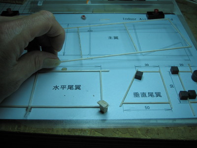
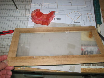
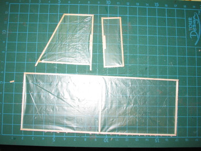
When the wing is finished moving the stabilizer:
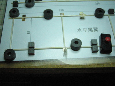
Then the fin and the rudder :
Delicately gets on the wing:
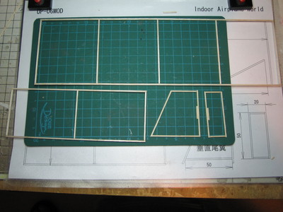
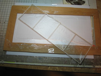
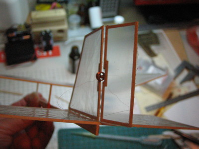
Overview canvas before covering :
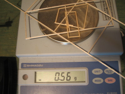
The mass of the frame is 0.56 g.
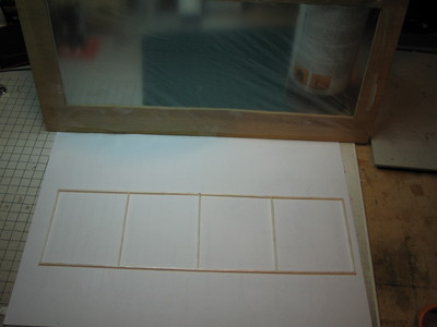
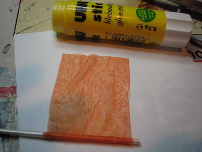
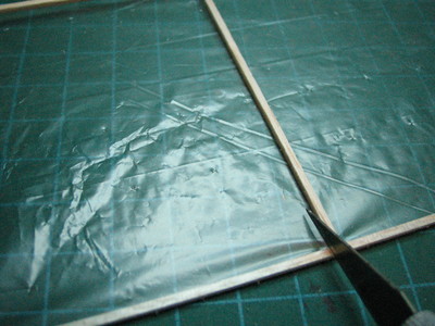
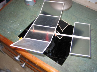
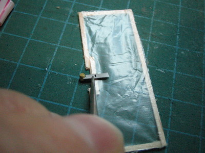
For the covering is used as a wrapping material newspaper:
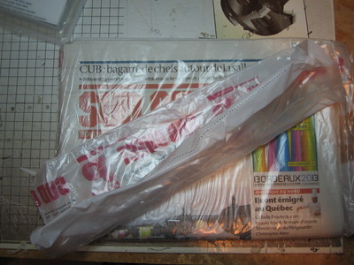
We will strive this material on a wooden frame:
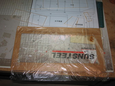
The tension is achieved using small pieces of tape :
The wing structure raises on an accordion of paper:
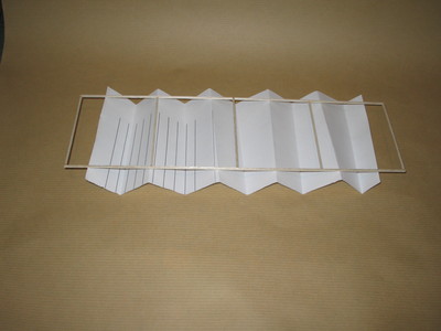
And glue is spray at a safe distance:
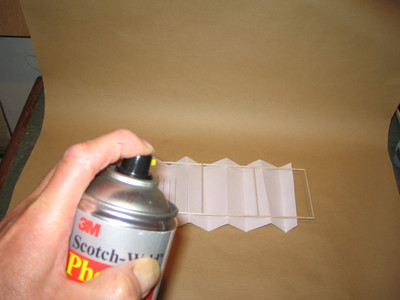
We set the structure on a clean surface:
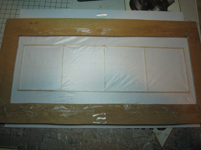
And on top spot on the frame with the film canvas:
cut the film with a the iron pyrograver (or an old soldering iron):
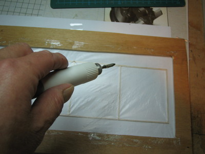
Here is the wing covered:
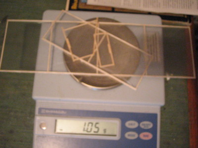
Overview :
New mass 1.05 g:
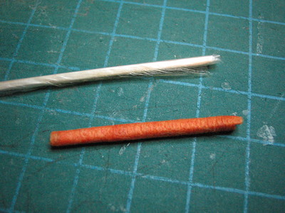
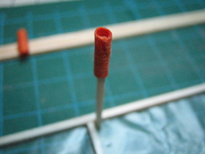
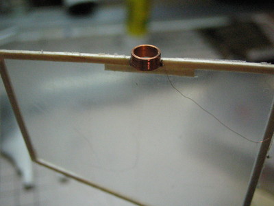
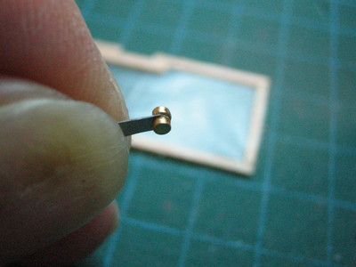
It will by now be a paper tube japan on a rod 1.5 x1, 5 rolls on a small length movie on canvas and then rolled a piece of paper sized japan:
Once on dry withdrew the paper tube japan of the wand, the film prevents it from sticking to the paper:
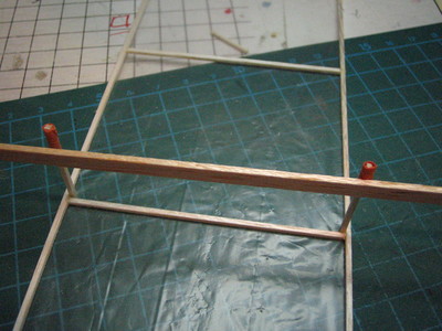
two other rods 3 cm are cut, which will bear the wing:
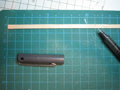
On the other hand preparing the fuselage is a rod 200x5x1.5:
The balsa sticks are glued on the wing following the plan:
a tissue tube is glued to 11cm from one end of the fuselage:
We place a tube on a rod wing :
Then install the wing on the fuselage:
A paper clip :
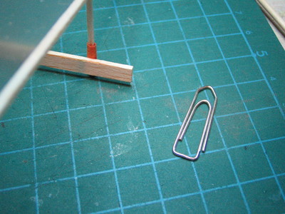
The paper clip is unfolded :
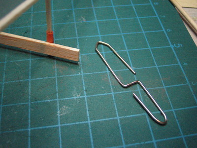
It will serve as the engine:
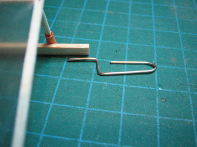
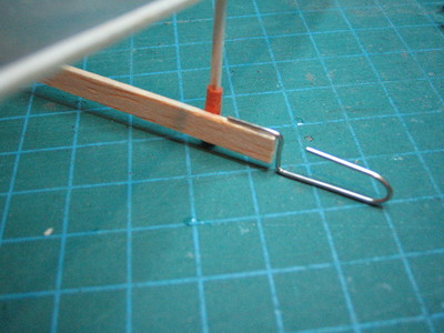
The piece is glued to the CA :
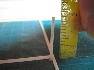
We must realise the dihedral, cut following the plan:
And we have the dihedral on the plan:
The use CA with accelerator :
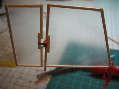
Here the aircraft without fin :
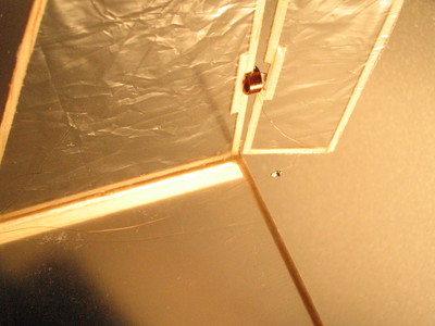
The 80ohm coil of wire 5 / 100 is glued (See Windings actuators):
The magnets diameter 2mm is glued on the arm (aluminum 3 / 10) :
The arm is then pasted on therudder :
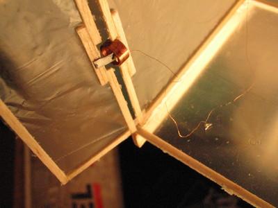
The fin is assembled with small pieces of Blenderm tape as a hinge (See set up an actuator):
The covering is bored with a pin where one will stick the fin :
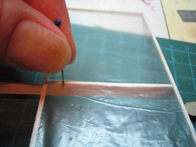
The fin is in place :
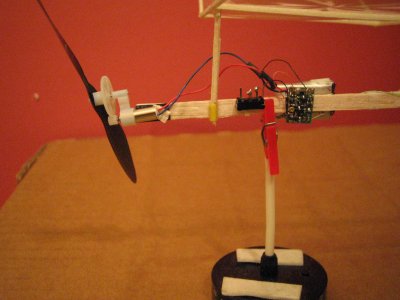
the engine issticked with CA on the paper clip (See Making a simplistic 1:6,7):
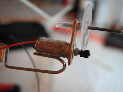
It no longer lacks the radio but the propeller is in place (see Making a propeller balsa simple and Tester traction propellers for micro-aircraft):
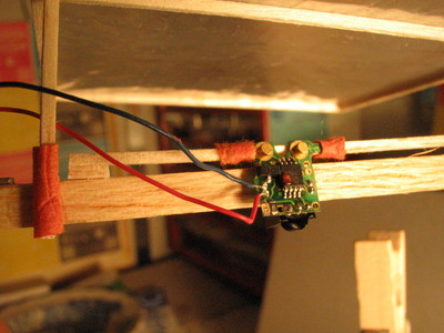
Here is the recommended receiver: Receiver infra-red Iz2 of Didel that operates with a transmitter PicooZ. To the right over the engine, left (bottom) those of the actuator, the two plots at the top are magnets for maintaining contact with the rechargeable battery (Bapi) .
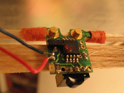
The reicever is maintained by two tissue tubes which slide on a rod 1x1, in order to better address the centre (but beware the wires of the actuator).
The wire winding being too short, we must make a welding wire to wire with a small ball of tin.
Welding wire to wire, you can clearly see the ball tin:
Another type of radio used, the combo0, 25g Micro Plane Solutions, tuning a radio is so delicate it should at least have a osciloscope.
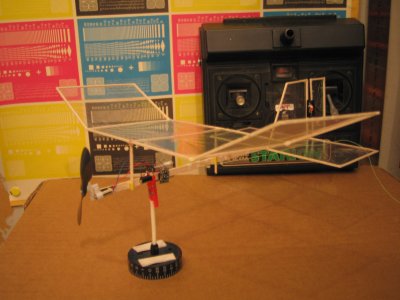
We must use a 72MHz radio on AM radio stations that have become rare, is an issuer Robbe STARION which has been used (you can see on the foreground of the photo):
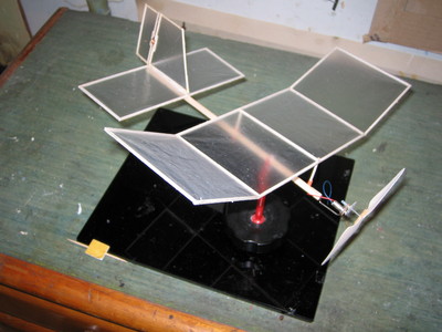
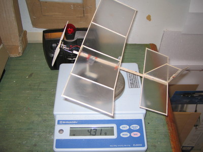
The model is finished, the mass of 4.31 g.
VIDEO