Next
The main differences are:
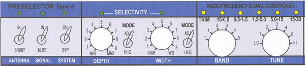
The coils selected are designed for specific bands (see LED indicators).
There is control for band overlap (Extend).
There is selectivity (Q) control for bandwidth "Depth" and "Width".
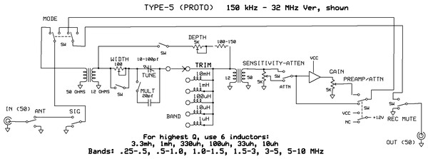
The resonant circuits are designed for maximum Q utilizing minimal capacitance values, and maximum inductance values.
Overall insertion impedances are kept high, in the 10 KHz and 20+ K Ohm range, with a loop impedance of 12 Ohms. This yields rejection ratios of approx. 1,000:1, or 60dB.
On the bench:
36dB Selectivity @ 3.5kHz (7kHz passband) = <1% selectivity (Actual at 1MHz=0.7%)
42 - 48 dB Selectivity @ ~10 kHz (10 kHz is one AM broadcast channel)
The final version employs different inductor values which give slightly higher Q values. The utility of preselection above 10 or 15 MHz (for me) is questionable, and since this unit uses a 6-position range switch, I decided to make the mods that are shown in the schematic. If you need the very broadband version, consider the 12-position inductor switch circuit of the Type-3 Preselector.
The bands are:
150-5 KHz
.5-1.5 MHz
1.5-5 MHz
5-15 MHz
15-30 Mhz
The "Multiplier" adds 30% overlap to the band switch.
Next
