
The blanker utilizes a pair of fairly high-speed diodes (silicon) across the incoming signal path. The basic principle is not unlike the traditional, standard Noise Blanker circuits found in many Shortwave receivers, but taken to a level which meets the practical limits of modern receivers' tight AGC circuits, high-ratio IF filtering, improved dynamic range and IP3, improved MDS (noise floor), operational stability, and overload recovery time.
External Signal Pre-conditioning: After some initial testing and circuit analysis, I have come to the very strong conclusion that noise blanking (and noise management in general) should be approached, first as a precept of "signal pre-conditioning." That is to say, prior to entering the receiver's circuitry. Noise, particularly impulse and other transient signals, can, and usually do, exceed the dynamic range of sensitive front ends, shift solid state junctions out of their linear operating range, overload AGC time constants and recovery times, and cause severe ringing in high-Q IF filters. Add to all this the fact that the nature of the actual noise signal is enhanced (yes, it becomes much worse!) as it progresses along the receiver's stages. Observing a transient on a scope shows that a typical 3 to 5 uSec spike will be stretched over the (real) time base, many times over, as it moves through the receiver's chain. This is due to group time delays, phase shift, and ringing. Of course, during this period, intelligable signal information is lost and usually many operating parameters are shifted far beyond their designed operational dynamics.
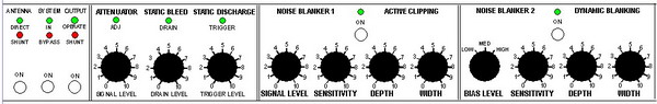
The Design Phase: I have added to the familiar "silicon switch" configuration, a three position, selectable biasing "sensitivity" circuit (bias voltage divider) and a corresponding "threshold" (fine tune pot) control. This circuit allows the clipping (blanking) diodes to be pre-biased toward conduction at any level from a few millivolts to well past full conduction (> 0.6V). Additional "depth" and "width" (duration) control may be added, if their functionality and utility appear to warrant it.
The depth control would provide a selectable amount of blanking, from 100% to (say) 10% and the width control would integrate the turn-on control voltage to provide user selectable "hang time." I am still toying with those function's validity and utility.
Prototype Testing: The biggest part of the R&D right now is (oddly enough) standardizing on a good broadband noise source that would simulate lightning crashes, ignition impulse noise, and other transients. I have begun the evaluation using a defective electronic ballast which produces very broadband hash across most of the LF, MF, and HF spectrums. I'm getting S9 +30dB signals from (about) 30kHz to 15 MHz. It's alright for the initial testing, but I'll need to refine my "noise generator" before finalizing the DNB. Next step is to put the ballast way out in the back yard at the end of a 100 foot extension cord and let it transmit into one of my antennas - hope the neighbors have a good sense of humor!
More to come, as it happens.

* Hole 'nother level!