 Pic of my Minor prior to modifications
 Pic of my Minor prior to modifications
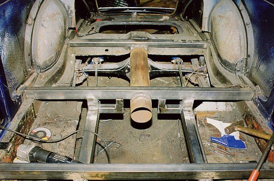
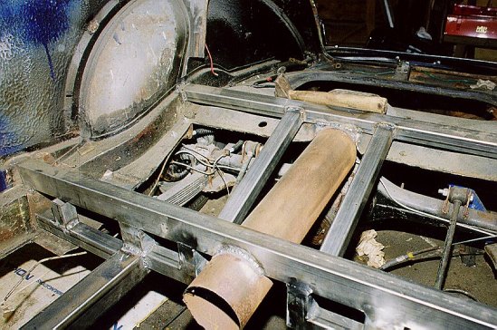
I started the body modifications at front. I braced the front of the car and removed the engine, gearbox and original suspension. I had prepared a pair of 80x60 mm rectangular steel tubes. I drilled the tubes for new suspension pickup points, welded brackets for Vitesse suspension towers and cut the tubes to correct length. The original suspension legs were removed one by one. First the left one was removed, new tube let in and temporarily welded in correct location. Then the right leg was removed and new one fitted. The suspension legs are now about 6 cm wider than original ones. Now there is enough space for bellhousing. Next step included several crossmembers. At front just behing the grille a 40x40 mm tube was welded between the suspension legs. Additional legs were also welded from the legs to the body, just underneath the bumber turrets. A special K-shaped crossmember (50x40 mm and 40x40 mm) is welded between the suspension legs, just where the front suspension lower arms are located. The shape allows the oil pan to clear the crossmember.
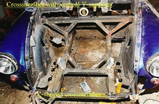
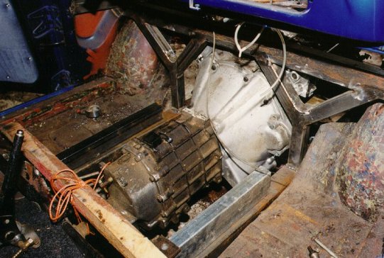
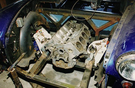
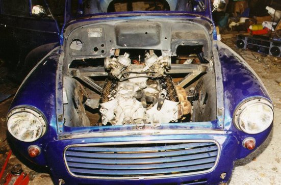
Original bulkhead crossmember had to be modified as well. To keep the body as rigid as possible I welded a new crossmember about 20 cm further back and a little higher than original. This supplies enough room for the longer engine. Crossmember (50x40 mm) is fitted with vertical supports (40x40 mm) forming a Y, thus giving more support. Crossmember has also another bracing oriented inside the cabin at about 45 degree angle like the original floor. The engine was trial fitted to its final position to check necessary clearances. To make things easier I used the bare block with gearbox attached. It was light enough for one man to move around. When the crossmember was complete and final-welded the original crossmember was cut away..
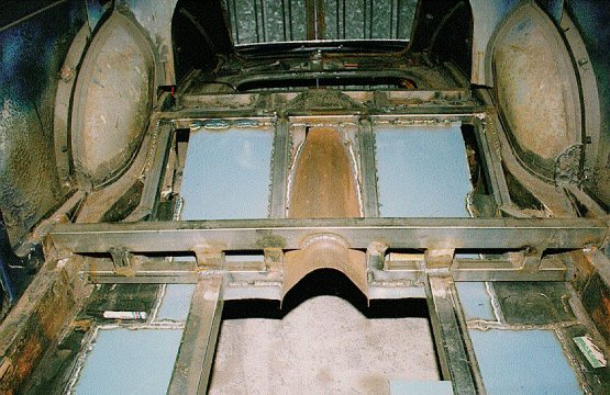
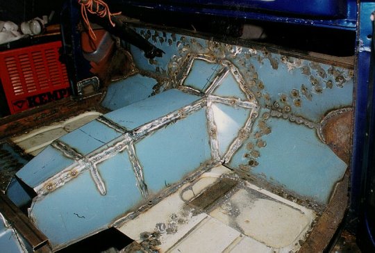
New crossmember (50x40 mm and 40x40 mm) was fabricated underneath the front seats, about 15 cm further back from the original crossmember. New crossmember has an intergral driveshaft loop. When the new crossmember was final welded in place the old one was removed. Suspension legs extent about 1 meter further back than originals and meet the new crossmembers below the rear seat. These structures were welded of 40x40 mm tube. Photos show the rear seat area strengthening. The idea was to join the suspension pickup points and keep the body as rigid as possible.
Steering required attention too. Originally the steering rack is located behind the front suspension, above the bell housing. My engine swap necessitated a front mounted steering rack as in Triumph suspension. This is due to engine and gearbox being longer than original so the original steering rack location was impossible. This was the first big problem. The new position planned was too far ahead. The tie rods did not turn enough so the steering rack would lock. New plans were required. I had to move the rack about 3 inches further back and lower it inside the suspension legs. This also meant that all suspension pickup positions had to redesigned and also some surgery to oil pan.

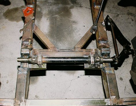
Since so many mods were required I chose to replace the Triumph spring towers with fabricated ones and also modify the shock upper mountings. New towers were 100x100 mm steel profile with 5 mm wall thickness. Original Triumph was pressed steel. This one should be a lot stronger. I also moved the pickup points of the upper wishbones to create more negative camber. Triumphs have a lot of positive camber and I redesigned the front to have about 1,5 degrees negative. With careful planning I found a location were camber is almost constant through the whole suspension movement.


After the strengthening was completed a total of 20 metres of steel tubes were welded in. New floors were fitted, following original design. At this stage I noticed that sills were not in the best possible shape so they were replaced with new reproduction sills. Floors are made of 1 mm steel plate. New floor was fabricated around the gearbox and surprisingly it is not as massive as what I expected. Rear floor was plated underneath the strengthening to keep the underside as clean as possible.


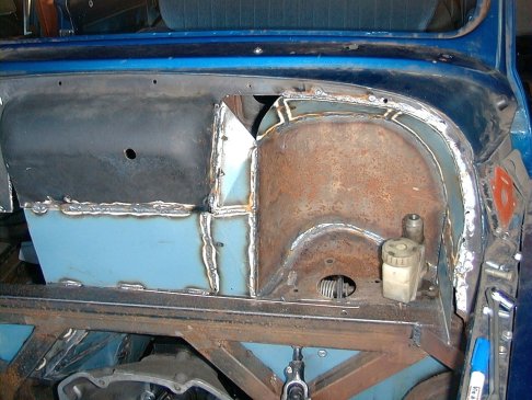
Front bulkhead needed serious surgery. I had chosen to fit master cylinders at the bulkhead which meant hanging pedals. Austin Metro pedal box was used and new bulkhead constructed around it. Additional bracing was welded in between the bulkhead and dashboard. Battery was relocated at the rear and battery tray removed completely. Hump in the middle was retained because it looks quite neat. RH side of the bulkhead was contructed of 1 mm plate with necessary holes for loom and heater hoses. End result looks reasonable if not exactly factory original....

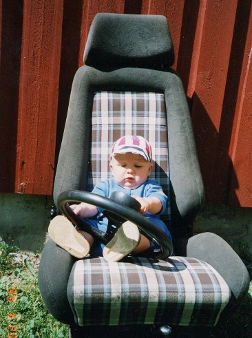
Dashboard was modified to accept extra gauges from Autometer SportComp range, rev counter, oil pressure and water temp. The woodrimmed steering wheel is an old and large item that was restored and fitted with an adaptor ring. Speedo is a mixture of Smiths parts with Morris Cooper S Mk1 face. Recaro seats came from an old RS Capri and are located further back to allow some driver leg room. A rollgage was fabricated and fitted for added safety. Back seat access is a bit limited and the car is now practically a two-seater.


| Minor V8 homepage | Suspension and brakes | Engine and gearbox | Technical updates 2000 | Back to Jukka´s HomePage | Updated December 4, 2000. |
|---|