The World's
Simplest Device Programmer
And Dongle
G. Y. Xu
Using the PC's printer port for serial
EEPROM programming can be made
extremely
easy. Shown in Figure 1 is a device
programmer circuit utilized
to
program the I2C serial EEPROM 24CXX. The circuit is so simple that any
further
simplification seems not possible. This programmer circuit has the
following
features.
1. It does not contain a microcontroller as
most device programmers do.
2. It doesn't need a separate power supply,
the so-called "wall-wart."
3. It doesn't need a cable. When in use it
is directly plugged into the
PC's printer port; although you still can
use a cable if you feel it
convenient(for instance, your PC's
printer port is located in back).
4. It doesn't have a single resistor, or
even a de-coupling capacitor.
As a
result, the programmer consists of only a DB-25M connector, and the
device to
be programmed. For a circuit as simple as this, what else can
you ask?!

These advantages come from the PC's
printer port resources and the
architectural
simplicity of the I2C serial EEPROM. As
we know, the printer
port is composed
of three 8-bit registers: the Data register, the Status
register,
and the Control register. Each register
has its unique address.
On the
classic IBM PC the Data port is used solely for output, the Status
port is
only for input, but the Control port can be used as either input
or
output.
On the other hand, the 8-pin tiny serial
EEPROM consumes very little
current
(well below 1 milliamps in active state), and the printer port's
data pin
can supply a few milliamps, so D7 (pin 9) is arbitrarily chosen
and
configured as power supply pin. No de-coupling capacitor is needed in
practice.
The I2C chip uses only two pins to control
its read/write operations:
the input
clock signal SCL, and the data I/O pin SDA.
This design chose
D0 (pin
2) to generate clock signal SCL, and configured /C0 (pin1) for SDA.
Because
the logic at pin 1 is the reverse of the logic level on control bit
C0, the
software must take care of that. This
is no problem. The I2C
interface
requires a pull-up resistor on SDA pin, such resistor is already
present
but located inside PC, so we don't need to add any pull-up here.
Once the hardware design has been settled,
the main job is to write
software. This is not difficult. For many embedded
systems software
engineers
it's a routine task and an interesting exercise. I have created
a freebee
executable program called PSEEP1.EXE for this purpose. It handles
only one
I2C device, the most popular 24C02's read/write operations as an
example.
You can download this program from my website.
Another important feature of this circuit
is that once the I2C device
has been
programmed, the whole system becomes a primitive dongle. It then
can be
used as a hardware protection device for your valuable software.
Because
only you know whatever was programmed in the device, no one else
knows.
When the protected software runs, it first checks whether the device
is
present at printer port, whether the code matches whatever programmed.
If that doesn't
match, the software will refuse to continue and exit.
Of course this is just a primitive dongle,
not a complex one. But it
does
illustrate the basic principle of the dongle protection technology.
You can build the circuit using wire-wrapping,
or using point-to-point
Soldering
technique, or simply build it on a solderless breadboard (in that
case a
cable is needed), or make your own PCBoard if you're going to use it
for long
time, as shown in Figure 2. For such
simplest circuit, it is just
a one-evening
project. Now let's play it for fun.
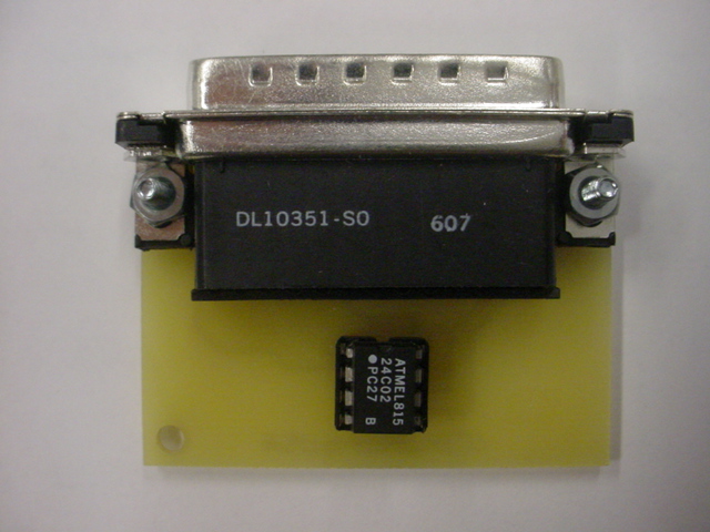
Figure 2. World's Simplest Programmer and Dongle