Leverage Artillery: The Trebuchet
Date completed: October 29, 2004
This class is intended to lay a foundation of medieval leverage artillery for students to take and build upon. It will by no means encompass everything there is to learn on the subject, and in fact will primarily focus on the counter ballast systems known as Trebuchet.
The course will be comprised of three main sections:
History:
Trebuchet is the French term, believed to be derived from the Latin ‘trabuc[h]us’. It signifies a specific piece of leverage artillery consisting of a seesaw-like lever arm with a sling affixed to it’s longer end and some form of ballast applied to its shorter. This siege engine’s origin has been traced to 4th century B.C. China, beginning as what we now call “traction trebuchet”.
| This is a sketch of a traction trebuchet recreated from a wall painting in the palace of Piandjikent, Transoxania. (Hermitage Museum, Leningrad) c.7th - 8th Century..
|
|
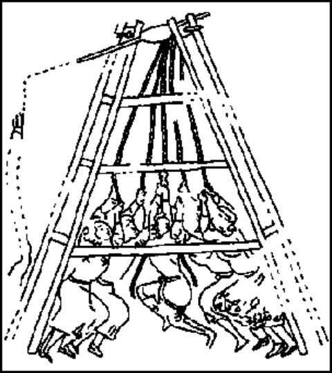
A traction trebuchet is a hand-powered machine that gains its potential energy from large groups of men (as many as 600) pulling on ropes rather then using attached ballast.
According to numerous texts, the trebuchet evolved toward a more familiar form in the 8-9th century when Arabic engineers acquired the Chinese designs, called manjaniq by the Arabs. They soon mounted large counterweights to them to both assist and reduce the number of men at the ropes. This transition design is sometimes referred to as a hybrid trebuchet. Despite the textual data, I have as of yet not found graphical images to back this date. The oldest image I have noted is one depicting the siege of Savonne CIRCA 1227.
| Traction trebuchet on the background castle and a hybrid in the foreground. (Siege of Savonne c.1227).
|
|
The earliest known, purely gravity-powered trebuchet is denoted in the records of the siege of Castelnouvo Bocca-d’Adda Italy CIRCA 1199, though numerous texts hint at an earlier existence. By removing the traction portion of the ballast system, not only was a more consistent and accurate throw was achieved, but also much heavier projectiles could be fired over greater distances. The physics and theory behind this advancement boil down to a two key points.
 |
Acceleration is the rate at which the velocity of a body is changed in a unit of time. Without getting too much further into the math of it, this means the longer the acceleration time the more force and therefore broader motion is applied. This statement combined with Newton’s Second Law of Motion, Change of motion is proportional to the force applied, tells us a falling weight would cause greater acceleration and therefore more force to launch a projectile.
Here is a simplified breakdown: Force = weight divided by acceleration due to gravity multiplied by acceleration.
The information offered for the traction trebuchet considers several “perfect world” presumptions; we could fit 100 men into the area cleared for our current fixed ballast, all the men can jump 3’ high from standing still, they can do so with 100 pounds of gear and they all grab their ropes at precisely the same time. Additionally the load of 100 pounds of gear is not very plausible, but was offered to keep certain variables constant.
Please keep in mind that these two forces are also measured at the load end of the trebuchet, not the sling end. The demo unit has a six to one (6:1) length ratio, meaning the distance between the arm axle and the sling prong is six times the length of the arm axle to the ballast axle. So these numbers would need to be multiplied by 6 for the values at the sling prong. Additionally the length of the sling directly effects the acceleration of the projectile. Typically a fixed weight trebuchet has a significantly longer sling then a traction unit. This is primarily because on a traction trebuchet, a man is often assigned to hold the sling and projectile until milliseconds after the “pullmen” have started the firing process. As soon as the “slingman’s” feet leave the ground he releases his hold to let the sling “snap” free. What I am getting at is these numbers are actually much further apart then I have shown here.
|
|
The other point of physics and theory behind the advancement is an affixed ballast system will consistently follow the same path and therefore create the same load pattern on the sling arm. The odds of 100 men all pulling ropes attached to the sling arm and creating a consistent loading pattern are miniscule. When a sling arm’s load is unevenly distributed, it causes the arm axle to flex unevenly, this then causes the arm to twist resulting in the engine being harder to aim. This tells us the benefit of an affixed ballast system is improved accuracy.
|
It is not entirely clear when gravity-powered “engines” were picked up in western Europe, but by the middle of the 13th century, we see evidence in writings and ordinance lists that western engineers were capable of building them in immense size. It is estimated that Villard de Honnecourt’s drawing of a trebuchet base (CIRCA 1250) would create an engine some 5 stories in height (about 50-55’) with a ballast capacity of 30 tons. There is documentation of earlier western use, such as in Scandinavia, but we are not positive whether these were pure gravity powered or hybrid trebuchet.
(Denmark, CIRCA 1134, Saxo's Chronicle stated when besieging Haraldsborg, king Erik Emune used a German built and operated trebuchet. - In De Bello Parisiaco, Abbo de St. Germain CIRCA 890, relates an eyewitness account that this type of device was used at the siege of Paris by the Vikings in 885-86. - The Annals of Saint Bertin, relates similar weapons were used at the siege of Angers in 873.)
You may note that in some of the images coinciding with this class the counter weight (or ballast) are fixed directly to the sling arm, while others show a pivoting barrel or basket mechanism. One has a definite advantage over the other in terms of destructive capabilities. If we refer to Newton’s other laws of motion, one basically makes the statement acceleration is better advanced via travel in a straight line.
| Path of Weights.
|

|
The fixed weight mounting method forced the ballast to swing in an arching path, which shifts loading from vertical to horizontal along the arm’s stroke. The centrifugal force of the ballast tries to rock and move the engine when it’s inertia is redirected horizontally.
Because this particular example possesses wheels, the entire engine has advanced as the fixed weight dropped. If the engine lacked wheels, the force dispersed while trying to move itself forward would have picked up the tail trying to keep the fixed weight on a path straight down, such as shown here:
Another example is to think of a swing set. When we were children it was our goal to swing as high and hard as we could on a swing sets. Anyone that has ever tried this on one that was not anchored in the ground, you have played the part of the fixed ballast. If you remember your efforts caused the swing set began to walk or threaten to tip over. The same is true with fixed weight engines without wheels.
When compared to the physics of the fixed mounting, pivoting baskets produced greater projectile range and more stability in the engine itself.
This is accomplished by allowing the ballast to travel closer to a natural free-fall path, which gathers greater momentum and a more consistent vector of force against the weapon’s arm resulting in an increase in range and a more structural stability. You my also note in the slides there is a distinct lack of an upturned vector where as here on a fixed weight engine, this upward force can cause the engine to hop after releasing its ammunition.
With the slightly downward sloping vector of the basket design, the force must overcome not only gravity, but also the friction against the terrain before the engine may move. In fact, until the return swing of the basket, this design actually holds the engine to the ground while launching its projectile. The result is a safer, steadier, longer and more accurate discharge.
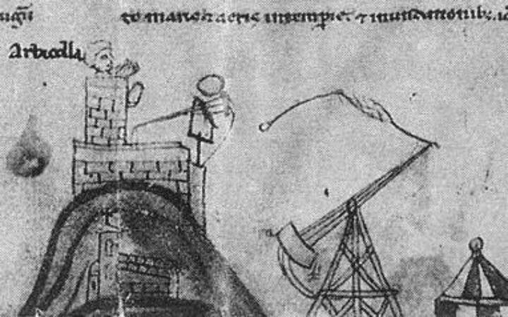
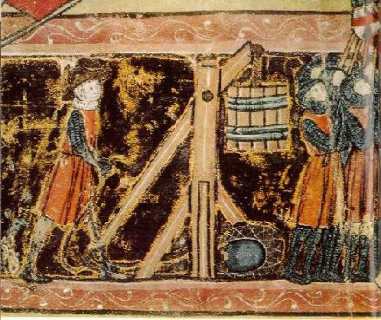
There are images that appear to show a secondary fixed weight and a pivoting ballast system at the end of the throwing arms. This is one such image presumed to show just that.
| Unknown artist and CIRCA, though the armor depicted implies the mid to late 14th century.
|

|
What we are seeing has been the cause of numerous debates. One interpretation is this could be illustrating a transition between fixed and pivoting ballast designs. Another thought is the siege master may have been experimenting. He did not want to disconnect his fixed weight until he verified the pivoting was indeed better. A third interpretation of the image is, the engine was mistakenly built just out of range and the fixed weight had to be added after the basket was totally filled to get the projectile to its target. I have not yet seen any documentation expanding this blending of fixed and pivoting design, so I cannot offer a definitive statement of what we are actually seeing.
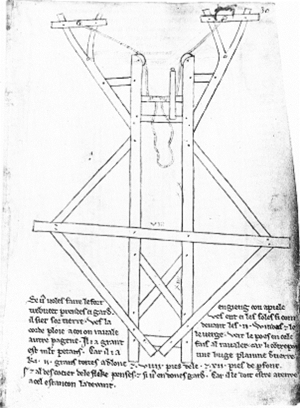
| Trebuchet base by Villard de Honnecourt, c.1250 (Only known surviving Trebuchet blueprint at this time.)
|
|
There are virtually no surviving “blueprints” for siege engines known in the world today, and the scrap that is known is severely lacking. Students of leverage artillery are reduced examining stacks of ordinance lists, period paintings and manuscripts to theorize how a complete engine may have been built. Details such as scale, ballast weight and range are all sketchy at best. One such area I find to be lacking is the cocking mechanism (or windlass).
The primary purpose of a windlass is to draw an engine into a cocked status. They prevent any loss of headway (unwinding) through the use of some form of ratcheting mechanism, but offer only a small mechanical advantage when readying an engine to fire. When confronted with the shear mass of the ballasts, the manpower required without the use of pulleys is staggering as is the force and strain placed on the windlass torsion members to winch the ballast into position.
As little as the windlass is detailed in the art surrounding siege engines, the illustrated use of block and tackle within such systems is virtually non-existent. We do know that pulley technology was in use as far back as ancient Rome and on sailing vessels through out history. We may; therefore, presume with a good degree of certainty that they were used on siege engines. It is a reasonable presumption, based on the comparison of the force required to raise a sail vs. that needed to cock a siege weapon, that the technology would have migrated to siege weaponry. We may conclude pulley blocks and systems were so commonplace in some cultures, that they may have been completely omitted from the various forms of documentation and reference, though this is purely presumption.
Using a block and tackle divides the force required to move a mass by the number of suspending ropes. The addition of two, double pulley blocks reduced the draw weight by roughly 1/4 the force originally required with a straight windlass linkage. This reduction in force comes with a cost however. The use of two, double pulley blocks multiplied the rope length required to draw the engine by 4 times and effectively cut the firing rate to 1/4 that with a straight windlass linkage.
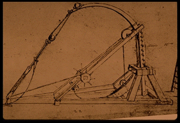
| A spring engine designed to launch two stones simultaneously. From II Codice Atlantico by Leonardo de Vinci. - Late 15th Century. Biblioteca Ambrosiana, Milan
|
|
In the late 1400's, Leonardo de Vinci depicts the use of what appears to be a set of pulley blocks as part of the windlass of a stone throwing springal. In it self, one might presume this was one of de Vinci conceptual sketches if it were not for pulley references in earlier illustrations. The 1453 edition of Valturio depicts pulley usage in a sketch of a spring engine used for launching large bolts. And while Villard de Honnecourt (c.1250) did not show a typical block and tackle system on his sketch, he did depict the use of pulleys with the roping. So we know the concept had been applied to siege engines in some fashion for quite some time. Through de Vinci, Honnecourt and the Valturio, we may be allowed to accept the use of pulleys on siege engines and make the leap to, if nothing else, the probability of their use in block and tackle arrangements.
| Violett-le-Duc's rendering based on Honnecourt's drawing CIRCA 1854.
|

|
This is a very popular illustration of a trebuchet drawn from Honnecourt's base sketch circulating in numerous sources. This drawing shows a simple block and tackle used on a basket-style trebuchet. I refer to that of Violett-le-Duc's rendering. This work was produced in 1854 and is therefore not valid SCA research documentation.
There are no known surviving trebuchet of the fore mentioned types in the world today; however, according to research by Rathgen (1928), an intact trebuchet was found at Liebenmuhl, East Prussia in the 1890's. It was apparently discovered (presumably un-assembled) when an old church was being torn down. It was “immediately cut up for firewood.” Because of instances like this, we have no authentic pieces to study, we are forced to combine archaeological tool finds, surviving paintings and manuscripts as well as architecture of the day to theorize the methods of constructing such machines.
Ordinance lists and the like assist us regarding the construction materials of these engines. Generally, a heavier wood such as oak was preferred for the framing while the throwing arm was often a lighter wood, most often something in the fir family. The slings appear to be primarily leather or of woven rope net.
In period, we find documents that lead us to believe that at least once, the ballast weight was transported to the erection sight from neighboring areas. Along with an order for 50 carpenters to construct a weapon “so powerful it would breach the strong walls of Stirling Castle”, Edward I demanded that lead be removed from all the churches in letters written just before the siege of Stirling (c1304). We presume this lead was used in a fixed weight engine known only as Warwolf. Because of its complexity to fabricate and expense, lead was not the most economical ballast.
| Bucket trebuchet, Bibliotheque Nationale de France
|
|
The advent of (pivoting) baskets (boxes & barrels) being mounted to trebuchet not only improved the operational dynamics of these weapons, but it allowed siege engineers and operators to rely on local terrain for ballast. Things like rocks, dirt and even water were used to power these great engines. This not only reduced the cost of manufacture, but of transportation as well.
The text accompanying Villiard de Honnecourt's diagram(s) backs the use of terrain as ballast. The following translation is from “War in the Middle Ages” by Philippe Contamine:
“If you want to make the strong engine which is called a trebuchet, pay close attention here. Here is the base as it rests on the ground. Here in front are the two windlasses and the double rope with which one draws back the beam (verge) as you can see on the other page. There is a great weight to pull back, for the counter-poise is very heavy, being a hopper full of earth which is two 'large toises' long and nine feet across and twelve feet deep. (il i a une huge plainne de terre ki .II. grans toizes a de lonc et .VIIII. pies de le, et .XII. pies de parfont) Remember the arc of the arrow (le fleke) when discharged and take great care, because it must be placed against the stanchion in front.”
Lab Lecture:
The trebuchet this class is based around is known as a helepoleis or trestle-framed trebuchet. The particular design was taken from the December 1997 issue of American Woodworker magazine. Russel Minner is credited with its origins. This version is 2/3rds the size of the original and is well scaled to use marshmallows as their preferred projectile.
Anyone wishing to build this design from scratch would need the following tools:
There are several points of interest that I have discovered in my self-education on trebuchet. A few I feel most significant or helpful to first time trebuchet design/builders are as follows:
| Trebuchet by Kolderer, c1507.
|

|
A perfect example of this is an image by Kolderer, believed to be illustrated in 1507. The sling is extended off the trebuchet’s base to depict the dead horse in the sling. Through my experiences (with sling lengths, not horse projectiles), I can pretty much guarantee this machine would never have thrown anything with such a long sling, in fact it is likely the horse would have caught on the trough either effectively stopping the motion or, more likely - and forgive me for the graphic description, shredding the corpse across the entire base and releasing (the sling) far to late and driving what was left of the poor creature into the ground very near the trebuchet.
The two key points to remember when adjusting your trebuchet’s trajectory today are:

Conclusion:
Trebuchet use did not begin to taper off with the advent of using the Chinese creation of black powder in projectile weaponry. Many scholars believe the noise and smoke created discharging these weapons did more psychologically then physically to end battles and “scar” one’s opponent when first implemented. It took a significant time for these new firearms to become functional enough to change the face of warfare.
Eventually the trebuchet did give way to the cannon. This evolutionally step was spurred by lower cost, better transportability, and eventually greater destructive power. A few leaders, such as Napoleon Bonaparte, entertained the use of these engines right into the late 17/ early 1800’s.
While leverage artillery has been around for hundreds of years, very few details exist to give modern day re-enactors and re-creationists a clear and concise picture of these grand weapons of warfare. It is up to us to research, and share all we can with one another in hopes that someday one of us will compile a true reference manual on the subject. I hope you have found my micro-course on Trebuchet inspiring and/or informative enough to set you on your way to future studies and experimentation.
-
NOVA: Secrets of Lost Empires - Medieval Siege (PBS)
-
Modern Marvels: Siege Machines (History Channel)
-
The Invention of the Counterweight Trebuchet: A Study in Cultural Diffusion by Paul E. Chevedden; Dumberton Oaks Papers 54, 2000, pp.71-116
-
Siegecraft: Two Tenth-Century Instructional Manuals by Heron of Byzantium by Denis F. Sullivan; Dumberton Oaks Studies 36, 2000 ISBN:0-88402-270-6
-
Experimental Reconstruction of a Medieval Trébuchet by Dr. Peter Vemming Hansen, Nyköbing Falster; Acta Archaeologica vol. 63, 1992, pp. 189-268: http://www.middelaldercentret.dk/acta.html
-
Historic Counterweight Trebuchet Illustrations, Grey
Co Trebuchet: http://members.iinet.net.au/~rmine/ht/htindx.html
-
Historic Traction Trebuchet Illustrations, Grey Co
Trebuchet: http://members.iinet.net.au/~rmine/histrac.html
-
Medieval Siege Warfare (Elite, 28) by Christopher
Gravett, Osprey Publishing
-
Siege Weapons of the Far East (1) Ad 612-1300 (New
Vanguard, 43) by Stephen Turnbull, Osprey Publishing
-
Medieval Siege Weapons: Western Europe Ad 585-1385 (New Vanguard, 58) by David Nicolle, Osprey Publishing
-
* Special thanks to Mr. Bechmann (who has personally handled Honnecout’s trebuchet sketch(s) in his studies) for his recommendations on which of his works, with specific pages, would best suit my research goals.