 |
||
        |
|
||
|
Mk 3 HULL DESIGN NOTES
There have always been many more considerations to the 4b hull design than the usual matrix for a fiberglas high-performance dinghy. Originally rowing performance was given as much weight as sailing, before it was realised how big a rig could be stowed in the box. The mk2 sailing performance suffers from the high rear rocker necessary for the coxed rowing mode, in which the stern of the mk 1 had dragged. Now the sail area can be more than doubled on almost all lightwind points of sailing with the genaker, rowing is relegated to rarer use in utter dead calms. So now the hull design is freed of serious rowing considerations, but many others remain
Firstly the principal boat concept is the 8 cockpit of flat plywood box bench, false floors, and transom with which the hull design must be compatible. The early hulls gave cockpits with wasted space and weight at the stern despite only a narrow traveller base, and lack of width at the front., such as for sleeping two or more commonly light wind seating.
A second extra consideration has always been ease and economy of making at least the prototype hull itself of plywood. Plywoods advantages are its factory phenolic glue, its thinness for light weight, its large width, and attractive face grain ; and its one weakness is its edge grain . Lapstrake is a very appropriate for the narrowness of solid lumber, but makes very little sense for plywood. Multiple chine joining of narrow plywood panels protects the edge grain better but uses even more expensive oil-derived epoxy especially with inappropriate biaxial glass tape.
So the 4b designs have consistently sought to minimise the number of ply panels and joints. Using a solid cedar hull bottom extending the bottom of the box, the first two prototypes got the maximum boat and good ply grain beauty out of two sheets of marine ply, with a chine joint only on the last 4 of each side. Fairness was high in the mk 1, but suffered a bit in the mk2, especially at the runout of the jointed chine.
Since then it has been realised that the boil proof phenolic bond actually allows marine plywood to be hot bent to very sharp curvatures suitable for a radiused rather than joined chines for a typical rear section. Such a radiused bend is inherently better for all sub-critical (planing) flow and runouts naturally. This hot bending is also suitable for a very fair lightwieght comfortable and wide rolled gunnel , now desirable to maximise hiking and trapezing moment with the big asymmetric spinnaker rig and always reducing the weight and difficult fitting of a wide gunnel. The ply grain beauty will be unbroken except by the scarfs.
Only bends (folds) of infinitely thin sheets follow ruling lines. A more accurate guide for severe elastic plywood development is modeling with birch plywood. When bends for the aft chine and aft rolled gunnel are heat-formed from the plywood edges , quite nice low rocker shapes of the rest of the hull half can then be elastically developed from the single birch ply sheet for spectacular unbroken grain. Once formed the hullhalves can be covered with a single piece of glass cloth and a poly cover sheet which produces a resin rich glossy surface hiding the weave and ready for varnishing, without any wasteful and toxic sanding of epoxy.
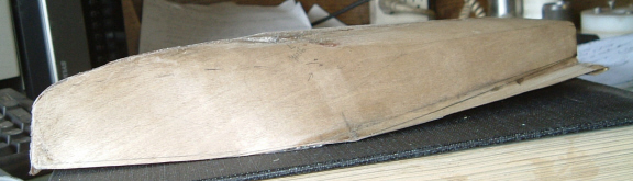
From near tumblehome at the transom, the sides progressively develop flare., whilst amidships the bottom starts to develop some transverse curvature, both running out the chine angle . Ahead of the cockpit, rocker and V progressively develop in the keeline and culminate in a sharp knuckle turn to a vertical stem. Transversely the knuckle is the final elastic trace of the chine.
The rolled gunnel is run out at the front of the cockpit just aft of the bend in beam from constant to straight convergence to the bow. This sharpish bend is well above the optimum unheeled waterline and should be camouflaged by the foredeck to cockpit transition. Such imperfections must be weighed literally against the assured performance enhancement of the lightness and stiffness of this construction, if not its ease and economy .
So there is now extra space forward with the flare for lightwind sitting low in the boat. Flare there also gives a wide structural diffusion of the mast loads to the hull and cockpit, without the stress concentrations of tight bends.
The gunnel delta wing for sitting up, out and back in a breeze will be supported by the wide traveller cross girder at the transom . Over its straight outer edge a slotted dowel will be fitted and terminated at the front bulkhead. On it will easily run a 3 length of slit aluminum tube with welded pivot for the hiking plank.
But does this shape match all-round flow requirements? In lightwind to shape the sails requires heel and then weight forward to stop the transom chine corner digging and to minimise the static wetted area. In Mk 1&2 this bow down mode was slightly unstable at moderate induced heel. Here the radiused chine helps to minimise the corner drag and the forward flare gives lots of heeled bow down stability.
In stronger winds, a dinghy is best sailed absolutely flat and as stern down as a clean wake permits. Planing will be improved by the very flat bottom (and lightness) of this design , and the higher prismatic coefficient. A recent trend is minimising rear (planing) wetted surface by transversely arcing the bottom between waterline chines. The current design allows some deadrise in the bottom between the box bench and the chines (matched at the ply transom by deadrise of the false floors). The flat center box bottom segment gives some beached upright stability , and the deadrise is limited to assure static stability of the empty boat at the dock.
The shape above the maximum displaced upright waterlines relates to waves and heeling and amidships seems the correct location for stabilizing flare without pitch being excited by waves or the heeling itself ..
Heeling in a dinghy is unlike in a keelboat, an off-optimum and transient condition for which the prime design consideration can be stability and control especially with a big rig. A typical wipeout scenario is a large gust impinging on the spinnaker. The low boatspeed makes the apparent wind abnormally high and the planing bow lift low., and the boat can nosedive and heel . Nosediving shifts the CLR forward and heel shifts the rig CE to leeward, both increasing the weather helm. Particularly with a lot of aft flare, the boat goes even more nosedown with (static) heel and the rudder can ventilate and lose control for a complete broach and nosediving capsize to leeward.