 -Half bridge circuit-
 For tesla coil; 300V / 400kHz /450W
-Half bridge circuit-
For tesla coil; 300V / 400kHz /450W
Introduction
I used this straightforward half bridge circuit for my first Tesla Coil experiment.
I
managed to squeeze out a
12 cm continuous discharge at about 600Watts of input power.
Then the MOSFET's overheated and blew up. After about ten pairs of MOSFET's I
gave up and started
a new design which is available on my homepage.
Altogether the circuit worked; but it is not very robust; I recommend the
second design on this page
which is easier to build and much more robust.
Main problems with this design are:
Circuit description
The circuit operation will be explained on the basis of the
schematic below.
The 3 main problems of half bridge circuit operation are:
1) Driving the floating high side transistor
2) Preventing cross conduction
3) Reverse charge of the mosfet body diode in capacitive mode.
Driving the low side mosfet T2.
The low side transistor is driven by inverting driver stage T3/T4
which are very fast low voltage mosfet's with
a current capability of about 500 mA.
The 4.7 ohm resistor in series with the gate prevents any
unwanted oscillations.
Note: the BST70/100 mosfets are very sensitive to ESD; I found
out twice during assembly of the circuit.
Driving the high side mosfet T1.
The high side mosfet is driven via driver transformer TR1.
The transformer is an EF25 core with 2 x 20 windings of 0.4 mm
diameter insulated copper wire.
I just took two insulated wires and wrapped them 20 times around
the coil former and then inserted the EF25 core.
The transformer construction is not very critical: any closed
ferrite core of about the same dimensions
or larger will work. The core should be quite large to be sure
that it can cope with the peak currents from
the driver stage which can reach up to 500 mA!
Capacitor C2 prevents DC current to flow through the transformer:
the drive signal has a DC component
as the duty cycle is lower than 50% because of the non overlap.
C1 is not really necessary; it can be used to achive some DC
shift in the secondary signal.
Non overlap
The non overlap is the time that both transistors are off; to
prevent cross conduction because of switchoff delays
it is necessary not to drive both T1 and T2 for a short time
during each transition.
This function is built with a hef4017 and a hef4002: output0--9
of the 4017 will consecutively become high;
this results in two non overlapping 30% duty cycle drive signals
on pin 1 and 13 of the hef4002.
The clock signal of the 4017 must be 10 x the desired output
frequency of the half bridge.
Note: I started with 40% duty cycle, but encountered some
problems with capacitive mode operation
I am currently lowering the resonance frequency of my tesla coil
som maybe I will return to 40% when this is done.
The oscillator
The oscillator is built with a 4046 VCO. The 4046 also has a PLL
on board, but it is not used here.
The frequency range is set at 800kHz-3MHz by R5,R6 and C5. The
output frequency is proportional to the voltage on pin 9.
For the time being I use a multi-turn 10k potmeter to set the
frequency but eventually it will be set by a regulating
circuit which measures the half bridge current.
Disabling of the mosfet body diodes.
D1 thru 4 avoid the bdy diode of the mosfet's to go in forward
conduction:
Schottky diodes D2, D3 block any reverse current while the fast,
soft avanche diodes D1,4 take over this reverse current.
Without this diode construction the mosfets will be destroyed
instantly when the load has a capacitive character:
one mosfet will pull out the huge reverse charge of the body
diode of the other fet, resulting in excessive
power dissipation. The BY229 diodes are very fast types which can
handle this situation.
Nevertheless it is always better to start at a high frequency
above the resonance frequency of your tesla coil:
here the tesla coil load has an inductive character.
When the frequency is carefully decreased, you will get closer to
resonance and the power will increase rapidly.
Unfortunately, the resonace frequency of the tesla coil strongly
depends on the environment; any object close to
the dischage terminal or the rate of ionisation of the air there
will influence the resonace point of the coil.
Due to this dynamic character of the tesla coil load diodes D1-4
are always necessary.
Half bridge schematic:
Transformer
The circuit is connected to the tesla coil secondary with a large
output transformer
built on a ETD49 core. Primary: 14 windings of 20x0.1mm litze
wire; secondary: 140 windings
of 0.40mm wire. Each layer is separated with some layers of paper
tape because of the high voltages.
One side of the transformer secondary is connected to earth; the
other side to the tesla coil.
Circuit application
First try the half bridge circuit at a low voltage (40Volts or
so); when this works you can connect the
transformer and the tesla coil secondary. Start at low voltage
again and monitor the DC current consumption.
Sweep down slowly starting from Fmax ; at a certain frequency,
the current is at it's maximum:
this is the tesla coil resonance frequency.
Note: The 4046 VCO is highly sensitive to capacitive coupling
from the tesla coil so use a plastic screwdriver
to adjust the frequency.
Repeat at higher voltage; try to remain above the resonance
frequency. For the first experiments I put a
grounded wire close to the discharge sphere of the tesla coil. I
increased the distance step by step until I reached
12 cm which proved to be the limit of my setup (after killing
about 20 pairs of mosfet's.....)
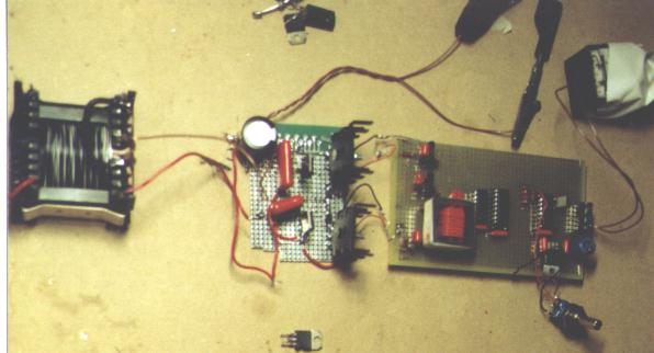
Picture of assembed circuit: (The heatsinks should be
much larger for full power)
On the left you see the output transformer.
→ Download specifications of key
components at the Component specs page