 Low loss speed
control
Low loss speed
control
PWM D.C. motor drive
Low loss speed
control
Introduction
This circuit is a very compact switching regulator for small DC motors. I use it for my small
printed circuit board drill
(18 Volt, 1.5 Amp), but it is suitable for many other applications (e.g. 12V
DC
halogen dimmer).
Circuit description
R1, R2, C1, D1, D2 and schmitt trigger IC1B build a 1kHz oscillator with
adjustable duty cycle.
The output of the oscillator passes through buffer IC1B/C/D which drives power
mosfet T1.
When T1 is switched on, a current will flow from the +Vmotor supply via the motor and T1.
When T1 is switched off, the motor current is interrupted; because the motor
acts as an inductor,
it will try to maintain its current, which can flow through freewheel diode D3.
The avarage current through the motor depends on the duty cycle of the
oscillator.
The circuit losses are very low, for my 1.5 Amp drill, no heatsink is required
for T1.
PWM DC motor drive schematic:

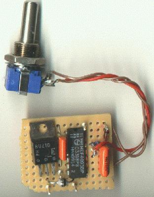
Picture of the assembled circuit:
→ Download specifications of key
components at the Component specs page