 0 - 1.5 MHz
 Square wave generator
0 - 1.5 MHz
Introduction
My signal generator stops at 200kHz; I needed a signal of
about 400kHz to tune my tesla coil.
so I built my own......
To tune the secondary tesla coil I connect signal ground to
"earth" of the power outlet.
The signal is connected to the bottom of the secondary via a 1k
resistor.
I measure the signal amplitude across the 1k resistor with an
oscilloscope.
At resonance frequency, the tesla coil secondary will draw much
more current which results
in a large signal amplitude increase across the resistor.
Be aware that the secondary resonance frequency is affected by
objects in its environment
and by ionized air in operating condition. In both cases Fres
will decrease.....
To measure the primary, I put the primary inductor and the
primary capacitor in parallel;
and inject the square wave signal with a 1k resistor but now I
measure the voltage across the
primary L/C . At the resonance frequency, the signal amplitude
will be at its maximum.
Circuit description
The signal generator is built with a 4046 VCO IC. This IC also
has a PLL on board, but this function
is not used here.
The maximum frequency is set by R1 /C1; the output frequency can
be set from 0 Hz to 1.5 MHz by
the voltage on the VCO_IN pin
I included a 1:10 frequency divider which is built with a 4017
counter because my frequency counter
stops at 100 kHz (yes you noticed well ... I do not have very
sohpisticated equipment at home)
Component specifications: (zipped .pdf files)
-HEF 4047 VCO / PLL specification (355kB)
-HEF 4017 COUNTER specification (87kB)
Note: the maximum frequency can be set higher than 1.5MHz by
decreasing R1. The minimum value for R1 is 10k
for even higher frequencies C1 must be decreased.
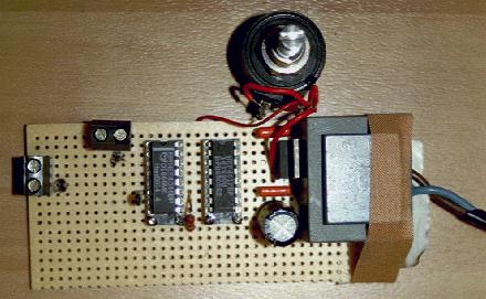
Square wave generator schematic:
Picture of assembed circuit: