 Manual EEPROM
programmer
For the XICOR 28C16
Manual EEPROM
programmer
For the XICOR 28C16
Introduction
I needed some flexible way to decode the RC5 codes of an infrared remote control; a bunch of and-gates and some hard wiring
will do the job, but it is not the most elegant way to do this.
An EEPROM is very much fit for this kind of operation, only how do you program them? Professional programmers are quite expensive!
When I read an EEPROM specification, the programming proved to be quite simple, this can be done manually too!
Because inside the IC some control logic takes care of the write cycle timing
it does not matter if you program the thing for 10 ms or 10 s!
Apart from that, you do not need any high programming voltages as with EPROMS,
EEPROMS are also much cheaper and do not need to be erased, just put new data in!
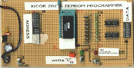
Picture of assembled EEPROM programmer
Circuit description
This programmer is custom made for the Xicor 28C16 EEPROM, for other manufacturers please check the specification
because the pinning is not always the same!
The 11 adress bits are set by 11 DIP-switches (A0--A10);
The 8 data bits (IO_0--7) can be set by 8 DIP-switches, the data can be monitored by 8 green 3mm LED's
which are fed by 8 transistor buffers
When the outputs of the EEPROM are enabled, the 8 data-DIP-switches are disconnected by 8 CMOS switches (2 x 4017 IC)
The output enable is set by switch S1, when the RED 5mm LED lights up, the data outputs are enabled.
The write enable is set by switch S2, when the green 5mm LED lights up, the EEPROM is in write mode.
The real write cycle is started when the Write Enable pin becomes high: the 1uF/1k resistor will prevent switch bounce on this signal.
Manual EEPROM programmer schematic:
EEPROM programmer manual
→ Download specifications of key components at the Component specs page