HOW TO MAKE A PIANOFOR[]
AT first sight the interior of a pian[] a mass of complexity, and, taki[] whole, there is certainly a great deal [] and wonder at ; but when it is rea[] that the whole action may be bough [] arranged, and even numbered, for [] tuinm a great portion of the credit [] transferreed to the action-maker, [] generally overlooked. The f[] in these days of divided labour the p[]ker," as formerly undersood, has entirely []peared, and in his place has arisen one []e sole work is to put the different parts []ther. So much has been lately said in []ur of "iron backs," that probably most of [] English readers would elect to sae them-[]s much hard work, and assure stability to [] construction by employing one. But on [] other hand I know of number in the []nies, and elsewhere, who have not the same []itites of procuring one, and who conse-[]ly would be obliged to content themselves [] the ordinary wooden back. For their []fit, then, I must crave indulgence whil []st describe how this is put together. The []s necessary for its construction are a wrest []l, bent side, linings (or end pieces) and []ings. The wrest plank is of English beech []less than 1 1/2in. thick, 4ft. 2 1/2in. long, and p[ wide. As this is perhaps the most impor-[] part of the whole instrument great care []ld be used in its selection. It should be []oughly weathered and "shop dried," and if []ible should be cut, as it is termed, "on the []er," that is, the tree is first cut in []ers, and the planks, cut off their faces. []o cut in this manner is almost impossible []lit, and as our readers are aware that a []er of holes are bored in it close together, []in a line with the grain, this is a []ty very necessary to guard against. The []side is also of beech, 1 1/4in thick, so called []se at one time it really used to be bent, []though not nut out of the straight it still []rves its old name. The round side should []r pretty nearly the curve of the bridge as []is means the same area of soundboard []rywhere between them. A sufficient idea []shape may be obtained from the diagram. []inings are of spruce, 4ft. long by 4 1/2 x [] The bottom is the same, but 2 1.2in. longer ; []acings, also spruce, are 4ft. long by 4 1/2 x [] There should not be less than six, and [] would be better still. To prepare these [] for putting together, the wrest plank [] first be planed level on both sides, and []ed. The side selected for the front must []be veneered with some clean white veneer, []ably sycamore, which should be, for the purpose of strength, 1/8in. thick, and the grain crossing that of the plank. While this is under the handscrews the spruce may be planed over, making the front sides level, and marking them as such. The linings and bottom are first required - a lap must be cut in the former to receive the plank. The depth of this lap depends on the thickness of the plank, which should stand over not less than 5/8in.; thus supposing the plank then levelled, to be 1 1/4 in., the lap should be 5/8in. deep, and calculating the finished instruent at 4ft. 2in., a fair average size, the bottom of this lap should be 3ft. 3in. from its lower end, which will be dovetailed into that of the bottom lining, this being, of course, exactly the same length as the plank. The first part to be put together is the frame -
[]next step will be the "bellying;" but, []for describing this, I will premise tha[]e, a the reader is no doubt aware, []ethods for both making and fixing the []ard - the one selected, from its simpli-[]tructure and freedom from dangerous [], being, in my opinion, the best adapted []be circumstances. We will begin by []g the back to receive it. As the []re at present level with the bracings, []st be reased by means of hardwood [] the proper height, the length of the [] being the full dpeth of the sound- []nd the same width as the lining ; []ckness commencing from under the []t 1/2in graduates to 5/8in. at the middle, []wn again to 1/4 at the bottom ; the []lip being less than 9in. in length , the []g can be dispensed with ; it will suffice [] in a straight line from 1/4in. at the top to []ere it joins the bent side ; the wedges [] to be reduced to that a straight edge, []sting at each end of the slips, will just []em.
[]oundboard is usually made of Swiss []st as an amateur will probably find this []procure dry, I think it will be better to []e the best quality 1/4in. American pine, []reful to select it dry, sound, and free []ots. The appearance of this may not [] so clean as the Swiss, but in all other [] I think the two will be found equal []e boards being much wider, the num-[]oints will be less. Before cutitng into [] (which run parallel to the wrest plank) []er to reject the first 6in. or so at the [] this part is usually faulty. Rubbing [] will hardly be found practicable with [] boards ; it will, therefore, be better []g them together. This is done by []g two lengths of wood firmly down, [] the space between them being about 1/2in. less than []th of the soundboard. This, when []with both sides touching, will of course []d in the middle, so that from a small []d an immense lateral pressure is [], and all superfluous glue will be forced []e soundboard will then be ready for []to a thickness. Hardly two opinions [] to what this should be. Without []ng to decide so knotty a point, I think [] thickness of from 5/16in. to 1/4 in. will []d as good as any, allowing it to be [] if anywhere, just above the plate, where it will be left without support. It can then be fitted, allowing a space of 1/4in. all round the bent side and under the wrest plank. Thile it is in position it will be better to tack temporary stops occasionally, or to screw the four corners so that it may be replaced exactly after each removal ; but, before it is taken out, mark where the bracings come, and strike a middle line evenly between them for the traverse bars ; these are of 3/4in. spruce, tapered to 3/4in. at the outside edge, 1 1/2in. wide for eight bracings, and 1 3/4 in for six bracing backs, and extending fully across the soundboard at their respective positions. The jointed side is usually left about 1/4 higher in the middle than at the ends. They are chamfered 4in. from each end to 1/4in. - see Fig. 2. To glue them on will, I fear, be a difficult task, as the handscrew chops will not reach far enough. Putting screws though the front would pull the bar to a joint, but their weight would affect the vibration. In the trade it is customary to spring a lancewood bar between it and the ceiling ; in this way all parts of the soundboard can be reached. Doubtless the ingenuity of the amateur will find a substitute, it being important that the joints should be close everywhere. A "bent side slip" is next required to support the soundboard at that part between the bracings. This is cut to the curve of the bent side out of 3/4in. beech of similar width, and graduating in thickness from 1/2in. where it leaves the treble lining to 5/8in. under the plate, from which position to the bass lining the soundboard can be left free.
We will now turn our attention to the fitting up of an iron back. The frames are generally made for a 9in. wrest plank, but as about 7 1/2in. only of that is necessary for pinning, the 8in. plank can be widened by jointing it at the top with a piece of any hard wood ; this, being covered with the bolt bar, will not show.
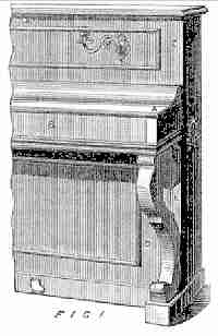
The linings, a, Fig. 1, are first to be bolted on, allowing them to rise 3/4 in above the iron ; they can then be marked and trimmed for the wrest plank and bottom, B, the latter being dovetailed as described for a wooden back. In preparing to the soundboard the linings can themselves be taken to the requisite height. A similar curved slip is also required at the bent pinning edge, D, Fig. 1, and as the bed, E, for the top of the soundboard is continuous, a slip will be necessary here also. These slips are only 1/4in thick, the insulating felt making up the difference. This felt can be at option either continuous like the lips, or only in small pieces for the screws to pass through, leaving the intervening spaces free. I may here mention I have tried indiarubber instead of felt, but with no improvement to the tone.
The next thing will be to ascertain the shap of the bridges. These are better of beech, though for the soundboard either close-grained birch or American maple will answer nearly as well. The top or plank bridges must be selected with the flowery side up and cut especially where the pins are in a straight line, a little across the grain. The scale and shape of bridges are set out at one and the same operation. The first step is to rule a line about 1/4in. above the bottom of the wrest plank (see dotted line, F, Fig. 1), to serve as a basis of measurement. As to give the lengths and striking distance of every string would tend rather to confuse rather than assist, I will confine myself to that of the C's, the top bridge being taken first. Commencing from the treble C, the distances above are 5/8in., 3/4in., 1 1/2in., and 2 3/4in., and the G one-fourth below 3 3/4in. Lines ruled between each of these measurements will suggest the necessary curve of the treble bridge, the remainder being contunued in a straight line parallel to the plank. Measuring from the striking distance of each C respectively 3in., 6in., 11 1/2in., and 23in. will give that of the lower bridge (see dotted line, H, Fig. 1), the remaining part, it wil be noticed ,now taking a hollow curve so as to rapidly increase the vibrating length to the extreme limits of the back ; the next C, being the first covered string, will be on the bass bridge ; its length is 33in. - this bridge, like the last, being carried as low as possible.
As at this stage the operator will probably not have provided himself with a hammer rail from which to take the top scale, it may assist him to know that the first bridge pin being 2 1/2in. from the outside treble lining, the first C will be 7 3/4in., the remainder having a space of 6 7/16in. between them along the line of strike. The bottom scale, which it will be seen is contracted, can be obtained by counting the pins on the iron back. The bridge can next be glued - that of the soundboard being fastened with 1/2in/ screws from the back, as their weight here will be rather an advantage, and it is essential to have the bridge firmly fixed. The next process, after gluing down the soundboard, will be "marking-off" for the pins. As, to do this, a top scale will be found necessary, I shall be happy, fo rthe convenience of such as require it, to send on on pricked paper for 1d. stamp. This can be tacked on a slip of wood, and the holes bored though for the marking-off pins to rest in, care being taken not to damp the paper as this would lengthen it to an extent that it would throw all wrong.
THE soundboard is now ready for fixing to its place ; with a wooden back it is screwed from the front into the wedges and bracings around the bent side, and nailed to the lining slips with clout-headed tacks (afterwards to be covered with varnished slips). It is better to have the holes bored and counter sunk so that the soundboard may be quickly fastened before the glue (which should be rather thin, and liberally applied) has time to chill. In an iron back, the linings only are to be glued, the remaineder being fastened with screws from behind, or with small bolts, the heads of the screws being insulated with a felt button before "marking off ;" the bridges must be planed to proper height, so that the down bearing of the strings may not be too great ; at the treble the plank bridge and lower bridge are level, and the straight edge laid across them should be 1/4in. above the bwent side or pinning edge, the remainder of the lower bridge being so regulated that straight edges laid on the bridge and touching the pinned edge should be of the same angle everywhier as the one at the treble ; the plank bridge can then be planed to the same thickness throughtout, which should be about 5/8in. ; the top and bottom scales are now placed in their respective positions, It may be necessary to explain that these are 1/4in. slips of wood, with holes bored at regular distances, those of the top scale corresponding with the hammers, those in the other rather []er together, or, as it is termed, "contracted," [] convenience or reference they are also let-[]d to the gamut in use, a pin is placed in [] hole consecutively, and with the straight []e leaning against them ; a line is ruled []en the bent side, lower and top bridges, this [] representing the right-hand string of each []e. The first or treble hole of each should be [] from outside the lining, the holes of the [] scale exably covering the strike lien, the []r laid on the bottom lining. As in an iron []e the pins are already in, the lower scale [] be dispensed with, the straight edge being [] at the right side of each pin instead, and []d across the bridges as before ; when they [] ruled they must be punched with two or []e holes as determined, taking care not to []ch near the edge ; they are then bored [] the bridge pins. I find for its purpose a []in. spoon bit, set in an Archimedean drill []k, to be the steadiest. The holes have a []ht lean - the top bridge and top row ot the []r bridge towards the bass end, and the []r row of holes the reverse way. The bridges []e then to be glass-papered and blackleaded, [] wood then cut away from the front of the []s, so that nothing touches the vibrating []on of the wires but the bridge pins. The []k is now to be marked and pinched for the []t pins. As it is necessary to have a "side []ng," these lines must be ruled with a bevel, []ngle bearing a proporiton of 1 in 3, and []sents the centre of wrest pin. To keep as [] as possible out of the grain lie, it is []r too bore the holes in four rown (or six for []chord) ; see diagram Fig.1, the lindes pen-[] and afterwards scraped out. The sizes of []for stringing are 12 notes of []4, 12 of 15, 11 of 15, 16 or 17, 4 of 18, and 2 [] of 19 and 20 ; for a trickord 1 size less of []s it extendeds ; but before putting the strings [] slip of baize must be laid all along the edges []e bent size and plate, to prevent the wire []g against them. The back is now ready []he case. In accordance with suggestions []k a case made after the French pattern []diagram Fig. 2), and of solid walnut, will []ost suitable for amateurs, as it will reuqire []er special tools nor cauls for its construc-[]
The ends are 1in. thick, 48 1/2in. long, and [] wide. In glueing on, a margin must be []all round the lining ; see dotted line (Fig. []e cheeks (C, Fig. 2), 1 1/2in. thick by 12 by []hen being dowelled (not glued) to their []on -
 | 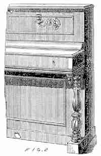 |
THE fall and back-piece are 3/4in. thick, and project sufficiently beyond the cheek to allow of the edges being rounded ; the front of the fall thus answering as a lift. The flap, B, fig. 1, will be hinged far enough back to give it the appearance of a panel, especially if the bottom of the lock-board is moulded as seen in diagram. It will also greatly improve the appearanec if the back-piece is mounted with a 2in. ogee moulding, which may be shaped in 1in. walnut, backed with pine. The top and bottom doors, C and D, Fig. 1, are simple framework, dowelled or tenoned together, the bottom door being fitted between false styles, E, to facilitate its fassage between the truss legs, and is panelled with 1/2in. walnut. The top door is carried to inside the ends, which will look better if thickened at the front to match the cheeks ; it also can be finished with panel and sconces, as in diagram, or with a fret and silk, according to taste. It forms a very effective swell if the panels of both doors are divided longitudinally, and hinged so as to open and close with pedal action. The top is a 1in. board projecting about 1/2in. all round to allow a thumb moulding. The legs most suitable to the style of case are either plain, bracket, or pillar, and drop, as shown in Fig. 2, either resting on a 2in. square-fronted show. The case work is now complete. The next task will be fitting the action, or as it is termed "finishing." For this purpose it will be necessary for the operator to provide himself with a set of 16in. keys to match the size of key-bottom ; they may be gought at from 38s. to £3, according to quality, and also a set of action or "small" work. This will consist of a set each of hoppers, levers, stickers, dampers (Collard's), and hammers, together with a hammer rail, and a socket rail, for the damper wires to work in, costing altogether about £2 2s. A check action would cost very little more, but would require considerably greater care in putting together - but, as it is, if properly regulated, a very great improvement both to tone and touch. A simple and at the same time very effective check action will be described further on. In finishing, the keys are first prepared ; a line ruled across them from 5 1/2in. behind the centre pin of the two outside A's will show the position of the front of the hopper mortice. To make sure of keeping the mortice in the centreit will be advisable to gauge from each side, the morticing being done with a 1/2in. chisel. Two other lines will also be necessary to guid the boring for the touch leads, the first about 1in. in front of the hopper mortice, the other as near the end of the key as practicable. They will be bored with a 3/4in. centre-bit (the hole being about 1-16in. []mested lead can be poured in, [] must be punched when cool, to make ][ the hole tightly, as otherwise it would ra[] The key-frame can then be clothed ; a[] centre cloth of firm texture, about 1/2 dia[] is required for the centre pins. This m[] shaped with a gun-punch for the front pins [] 3 to 5 slips of ordinary baize will be nec[] for each row of key-pins ; or , if prefer[] set of key baizes may be bought, rea[] fixing, at the cost of a mere trifle, fro[] small work makers. At the back rail, f[] key to fall on, are put 2 slips of baize, the[] edge being protected by a groove made []ceive them. The keys are now read[] easing. This will require a small flat [] rat-tail file for the square and round[] these holes must be filed till the key [] gently drop to its place without pressure.
 |  |
THE action frame consists of two end pieces or standards, and two rails - viz., the lever rail and the hammer rest. The standards are made of 1in. hard wood - generally bay wood - 3in. wide, resting at the bottom on a block 1in. square, and are kept in position by dowels. The top of the treble standard is cut so as to allow it to pass freely under the wrest-pins, and the bass to match ; a 3/4in. block 2in. long is then glued to the part leaning against the plank, A, Fig. 1. The hammer rail is first squared across at the ends of the brasses, this line forming a shoulder to a 2in. tongue at each end, let into the standard, so that a 1/8om/ slip placed over them shall be flush at the edge. (See diagram B, Fig. 1). The tongues are then blackleaded, to ascertain the position of the rail. Put the treble standard in its place, and mark the height of the top bridge pin on it. 4in. below this mark is the position of the centre wire. The lever rail is of 1in. pine, 1/4in. longer between the standards than the hammer rail, and giving it that much play. 3/8in. laps are cut at each end, and dovetailed into the standards (C, Fig. 1). The height of this rail is regulated by that of the hopper. For a 2 1/2in. hopper it will be 4 1/4in. from the key bottom to the top of the rail. An action spring is then screwed outside the treble standard, pressing against the tongue of the hammer rail. The blocks are glued to the key-bottom, their position indicated by adjusting the hammer butts to their respective strings, the same distance (about 16 1.2in.) being everywhere between the back of the rail and inside the lockboard. A dowel is then put in teh top blocks, projecing 3/8in. beyond them ; a slight tap at the fron of the standards will mark their place on the wrest plank, the holes being bored slightly below. To get the length of the hammer stems fit a treble hammer until the nose just clears the bridge pins, and cut the remainder to the same outside measurement. The key-frame can now be screwed to its place, taking care that its bass key is at the same distance from the standard as the hammer butt. The levers are usually put in to a scale fixed between the standards ; but it will, perhaps, be a readier method to first put in the hoppers, carefully spacing them, and set the levers in to match them. The damper rail is of the same wood and dimensions as the standards, and 3ft. long. It is centred at the treble end in a "damper rail eye," screwed into the plank, and at the bass, with a "side centre" sunk in the rest. This is a piece of 1in. wood, 2in. deep, fitted between the wrest plank and the projecting front of the end. At the back of the rail is a square length of 3/4in. pine, on which the dampers are hung (A, Fig. 2). The front is clothed with soft baize. The height of the rail is ascertained by trying dampers at each end, allowing a working space of 1.2in. between them and the hammers. They are finally hung by the hammer scale. To obtain the length of stickers, measure between the levers and the hammer butts, and deduct 1/4in. for thickness of hinge and play of sticker ; or if the measurement is required before fitting the action, deduct 8 1/2in. from the space between the top bridge pin and key-bottom. To mark for the damper wires : Bend about 1 1/2in. from the bottom or plain end of a wire to a right angle, and screw a button on the top. Place this just under the damper, and mark where the bent end touches the left si[] stickers, Nos. 1 and 60. The dampe[] are then placed sides up, and a [] between these marks. A small ho[] bored 1/4in. from the front, and thw wi[] through and cut close to the side of t[] when they will be ready for fix [] hammer rest is a duplicate of the [] bevelled at the inside of the top ed[] the slant of the hammer, and clot[] soft baize. It is placed so that the [] when resting on it are from 2in. [] from the strings. The next task [] cutting the tops of the hoppers - [] conducted with extreme care, suffici[] taken off to allow the hammers to [] on the rest, without any space or play [] the lever and the hopper . The back[] taken off (A, fig. 3), so as to let [] down gradually on to the check, at[] as much as possible the double blo[] hammer - that bane of single act[] giving to the tone a most unpleasa[] as may be readily understood when []sidered that this second contact [] hammer with the string is at a ti[] the latter is at its fullest vibrati[] hopper checks are cut so as to a[] hammer to fall about 5/8in. from the [] and with a slight backward slant (B, [] The whole are then blackleaded and b[] The damper wires are then adjusted [] they stand perfectly free between the h[] The socket rail is slipped over them, [] in its place by the props, which are p[ into the back of the hammer rail. The [] or damper lifts are put on, leaving [] of a card between them and the [] The rail shade (which is a slip of 1./4in. wo[] a shelf for the dampers to rest on w[] rail is raised by the loud pedal) - See dia[] Fig. 2 - is fastened to the front of the [] rail, and concludes the finishing. Th[]ing portion, including the pedaling an[] the various blocks, &c., is called fly-fi[] the last of all being the regulating a[]ing the keys.
W. H. DAVIES.Queries [from The English Mechanic], 1878