THE ORACLE 100
S100 Analog Speech Synthesizer
A simple inexpensive voice synthesizer for the S100 bus. 1977
Ever since I heard a speech synthesizer at Bell Labs when I was a teenager, I have been fascinated by the prospect of computer generated voice. Several racks of expensive equipment were needed to generate and control voice sounds, far beyond the resources of an amateur experimenter. Today, it is possible for anyone with a minimum investment to obtain the necessary equipment.It seems as though all of the speech synthesizers an the market today are both expensive and secret. Large blocks of epoxy guard the inner workings of arcane circuits. As a dedicated do-it-yourselfer, buying blocks of unknown epoxy seemed a sin so I designed my own circuitry. Also as a card carrying tightwad I made certain that only simple, cheap and available components were used.
Before I could start designing I had to arm myself with some knowledge about voice generation so I went strait to the old masters at Bell Labs. They publish a book called "'The Speech Chain"' which covers the basic physics and biology of spoken language. For further enlightenment I consulted with "Speech, Analysis and Synthesis" by J. L. Flanigan (also of Bell Labs). Now well armed, I began my design.
The human vocal tract can be modeled by a series of tubes of varying cross section, acousticly driven by a set of vibrating bands called vocal cords. Such a tube exhibits a set of resonances called formants which can be seen by an audio spectrum analyser as peaks in the spectral output of the voice. As we speak we vary the position and crass sectlon af our acoustical tube with movements of the tongue, lips, cheek and scft palate. It is the resonances and their changeing paterns that provide much of the information our brains decode as speech. BUT FIRST SOME THEORY
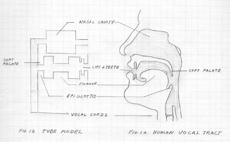
Figure 1. Diagram of the vocal tract and Tube model.
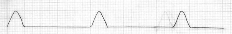
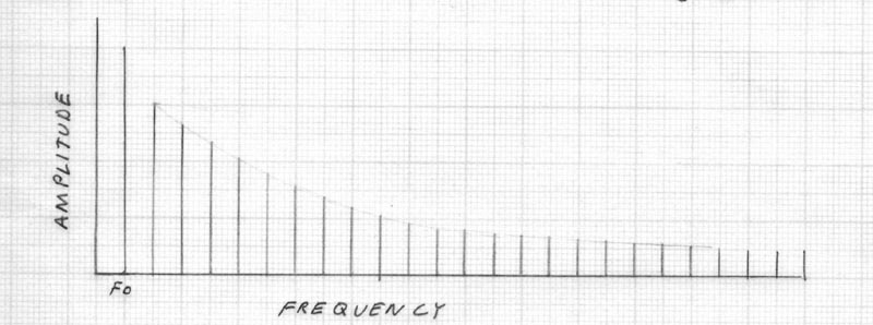
Fig.2. Time and Frequency representation of speech waveforms.
Fig.2a. Vocal Cord Waveform
Fig.2b. Vocal Cord Spectrum.
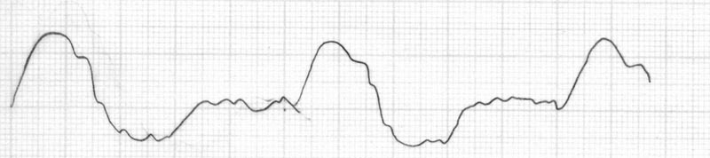
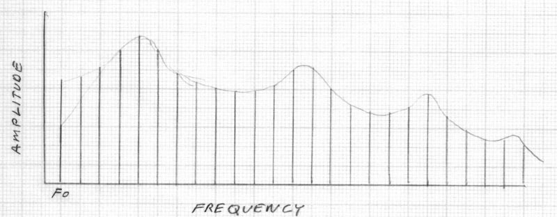
Fig.2c Voice Waveform.
Fig.2d. Voice .SpectrumThe ORACLE 100 is termed a terminal analog type of synthesizer. That is it makes no attempt to model the acoustic tube and other measurements of the vocal tract, but simply tries to duplicate the waveforms that can be seen on an oscilloscope connected to a microphone.
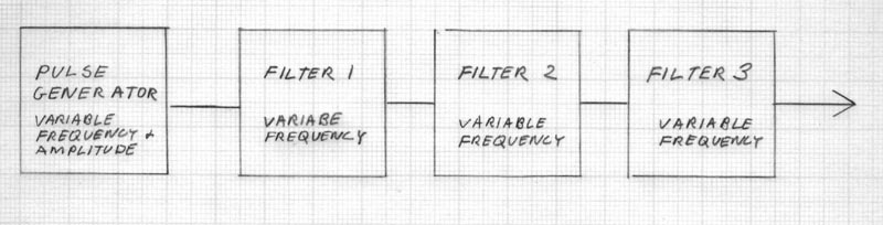
A simple svstem that can duplicate most vowels is shown in Fig 3.
Fig 3. Block diagram of vowel generatorThe important characteristics of the vocal cords, amplitude and frequency, are variables that modulate the output of a pulse generator. The pulses are then fed into a series of filters which have variable peak frequencies. These filters reproduce the peats in frequency responce (formants) in the speech spectrum, It is generally agreed that the the first three formants are sufficient to represent most vowels.
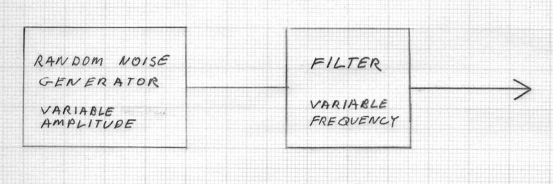
Now all speech isn't [ah] [oh] [ee] so we must make provision for consonent sounds. First we attack the fricatives, so named for the frying sound (white noise) we perceive in [s] [sh] [f] and [th]. All of these sounds are made from air passing through a constriction in the Touth lips or tongue. Spectral analysys shows them to be white noise with some accentuation in frequecy responce. The [sh] sound has the lowest frequency followed by the ty, [th] and [f] sounds.
Fig.4 shows the fricative generation system.Now for some fine points. The H and whisper are produced when a small amount of fricative noise gets in the vocal tract. This is simulated by in injecting noise into the vowel filters. The nasal sounds [m],1[n] and [ng] are produced when the soft palate is open and the mouth closed by lips or tongue. Most of the sound energy escapes through the nose and through the throat and cheeks. After studying the output of my voice with a spectrum analyser I determined that lowering the Q of the first two,formant filters would best appoximate these sounds. Next, [b],[d], and hard [g] are produced with both the mouth and nose closed. By drasticly lowering the resonant frequency of the first formant filter I reproduced these sounds.
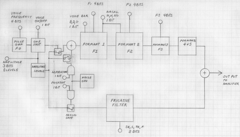
In designing the ORACLE 100, I tried to reduce to a minimum the number of bits needed to control each function. This accomplishes two goals; first, to reduce the cost of the circuitry needed and second, to reduce the amount of memory needed to store a resonable vocabulary. The bits used were derived from studies made by researches at Bell Labs and elsewhere.
Fig. 5 Block diagram A ORACLE 100 showing bits needed
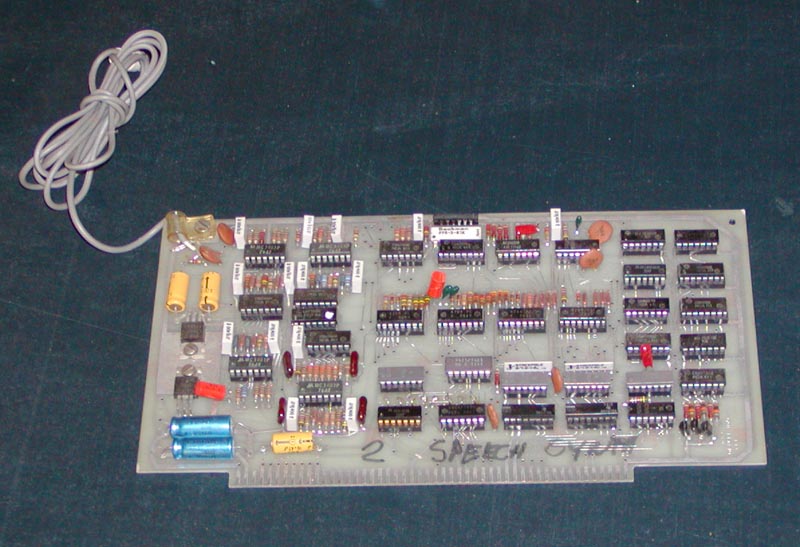
Actual circuits.
REF Oracle100 Schematic 1
Oracle100 Schematic 2
Oracle100 Schematic 3
Oracle100 Schematic 4
Realizing that not everybody is an electronic engineer, I will divulge my circuit diagram. (While researching this article I read some 10 year old entries in "Proceedings of the IEEE in Acoustics" that had the same circuit ideas I just dreamed up in 1977)
First, the ORACLE 100 is configured as an I/0 device with a single IO address on the I/O Port starved original S100 (only 256 ports). Jumpers allow any one port to be selected. If the the proper I/0 address is on lines A00 through A07 board select is activated. A control data byte is stored by anding SOUT, /WRITE, and board select.
The byte is stored in a pair of 74LS75 latches, then converted to CMOS (12Volt) levels by 7416's and 4.7K pullup resistors. The control data is then routed to four F4724 addressable latches by a strobe generated by a 74121. Bits 5,6,and 7 of the control byte determine to which address bits 1,2,3,and 4 are latched. Bits 1,2,3,and 4 are the 4 bit data nibble which control the operating parameters of the analog circuits of the synthesizer. Once latched each nibble remains stored untill changed or a reset occurs. This system creates a powerful changed value coding scheme in which speech parameters that do not change during a particular time interval are not coded, saving the user approximately 30% of the memory otherwise needed. See Fig. 6 for the ORACLE 100 coding scheme.
Address OOO is decoded as a mode control. Because of the nature of the vocal apparatus it is not necessary for every mode of operation to be available at the same time. For instance there is normally no nasal and sibilant combinations. Code 00000000 (00) is reserved for end of message (EOM) which tells the processor the word is finished.
Address 001 is decoded as a time delay parameter. For a minimum delay of 10 milliseconds bit 0 of the control byte is set. This creates a pause before further information is sent to the synthesizer. For delays of up to 150 ms a code with the 001 address can be sent.
The computer looks at the status of the delay by doing an input from the board address and watching DI7. When DI7 is set the computer should delay before dumping more data into the synthesizer.
Address 010 sets the fundamental frequency of the pulse generator (1/2 NE556) which is the source for all voiced sounds.
Addresses 011,100,and 101 set the formant frequencies. Each formant filter is basicly a high Q low pass filter. Each filter is made from 3 operational amplifiers connected in the state variable or bi-quadratic form. Two resistors are varied to change the center (or cutoff) frequency. This is done by using resistors in series with an analog switch (CD4066). The effective resistance of this circuit is changed by pulse width modulating the CD4066 at an ultrasonic rate. A triangle wave ascillator made from an LM339 comparator and one section of a CD4070 provides the modulating frequency of approximately 25.6 KHz. The formant nibbles control a set of four resistors weighted in a 1-2-4-8 fashion. the voltage produced at the junction of the resisters is compared with the triangle wave with LM339 comparators, with the resultant waveform controlling the CD4066's on each filter.
The triangle oscillator provides a clock which feeds a CD4026 counter and a CD4006 shift register. The shift register operates with a CD4070 exclusive-or chip to produce a pseudo-random sequence generator. (PRG) The output of the PRG constitutes the noise sourse for the fricative sounds. The output of the CD4020 is the 10 ms delay clock.
Address 110 is the amplitude parameter. A set of resistors in a 1K dip pak .2K sip pak are connected to farm a set of 3db voltage steps (a division by 1.414). A CD4051 analog multiplexer makes contact to the appropriate voltage for each amplitude step, This voltage is modulated by either the voice pulse or the noise sequence. The amplitude data also modulates the width of the voice pulse. Lower amplitude voice is associated with a wider glottal pulse.
Address 111 has only one function as yet, to set or reset the interupt mode.
SOFTWARE SOFTWARE I WHO WILL BUY MY SOFTWARE?
To create understandable words, the data controlling the ORACLE 100 must be highly structured. Several types of software structures can be implemented. The most straight foward system is to have the data for each word in a separate list. fhe starting address for each word is found in a dictionary and a simple subroutine reads the code and passes parametersto the synthesizer. This is an example of the drive subroutine.
;SPEAK SUBROUTINE [8080 code]

;REG PAIR HL CONTAINS A POINTER TO THE FIRST BYTE OF CODE

SPEAK :
	MOV A,M		; Get Byte From Memory

	OUT SYNTH	;Output to Synthesizer
	ANI	ffH	;Check for EOM character
	RZ		;Return if EOM found
CKST:
	IN SYNTH	;Get Time Status From Synthesizer ,
	ANI 80H		;Check if Ready for new Data
	JNZ CKST	;If nor ready keep checking
	INX HL		;increment pointer for next byte
	JMP SPEAK
.
The word list produces the best fidelity speech, but requires the most memory. About 30 to 150 bytes per word are needed depending on length and number of sylables. A full set of ASCII characters requires about 3K bytes. An alternate way of driving the synthesizer is to break words into components which are called phonemes. Phoneticists have selected 43 phonemes for the standard American English. Each phoneme is assigned an ASCII character to represents it. Combinations of phonemes are operated on by a "Synthesis by Rule" program which calculates the spectral tragectories of the formants. Such a program must be quite complicated in oder to produce decent output.
Figure 6 ORACLE SYNTHESIZER CODE STRUCTURE
D7 D6 D5 D4 D3 D2 D1 DO Type Data 10 ms delay 0 0 0 Mode TD 0 0 1 Time Delay 0 1 0 Fund. Freq. TD 0 1 1 Formant 1 LD 1 0 0 Formant 2 TD 1 0 1 Formant 3 TD 1 1 0 Amplitude TD 1 1 1 Interupt TD
MODE CONTROL TIME DELAY VOICE FREQ 1st Form 2nd Farm 3rd Form Amp 00 EOM 20 0 ms 40 75 Hz 60 250 Hz 80 600 Hz AO 1500Hz C0 0db 02 Silent 21 10ms 42 80 62 300 82 750 A2 1625 C2 3db 04 i 22 20ms 44 85 64 350 84 900 A4 1750 C4 6db 06 Asp. 23 30ms 46 90 66 400 86 1050 A6 1875 C6 9db 08 Normal 24 40ms 48 95 68 450 88 1200 A8 2000 C8 12db 0A Nasal 25 50ms 4A 100 6A 500 8A 1350 AA 2125 CA 15db OC Voice Bar 26 60ms 4C 105 6C 550 8C 1500 AC 2250 CC 18db OE -- 27 70ms 4E 110 6E 600 8E 1650 AE 2375 CE 21db 10 SH 28 80ms 50 115 70 650 90 1800 BO 250,0 12 S 29 90ms 52 120 72 700 92 1950 B2 2625 14 F 2A 100ms 54 125 74 750 94 2100 B4 2750 16 TH 23 110ms 56 130 76 800 96 2250 B6 2875 18 J 2C 120ms 58 145 78 850 98 2400 B8 3000 1A Z 2D 130ms 5A 146 7A 900 9A 2550 BA 3125 1C V 2E 140ms 50 145 7C 950 9C 2700 BC 3250 1E TH 2F 150ms 5E 150 7E 1000 9E 2850 BE 3375 Vowel codes
Male Beet Bid Bed Man Father Haw Hood Moon Hut Her L M N NG 60 66 6C 70 74 6C 68 62 70 6A 62 60 60 60 96 90 90 90 86 84 86 84 88 8A 86 86 8C 90 B8 BO BO BO BO BO AC AC BO A4 AC AC AC B0 Female 62 68 6E 78 78 6E 68 64 74 6A 64 62 62 62 9C 98 96 94 88 84 88 84 8A 8E 88 88 8E 92 BC B8 B8 B8 B8 B4 BO B4 B4 A8 AE BO BO B4 ee i e ae ah aw u 00 n er Partial Parts list
Integrated Circuits TYPE QUANTITY DESCRIPTION LM556 1 Dual Timer MC3403 4 quad op-amp LM339 1 quad camparator LM7805 1 +5 volt regulator LM7812 1 +12 volt regulator CD4001 1 CMOS quad nor CD4011 1 CMOS quad nand CD4006 1 CMOS 18 stage shift register CD4013 1 CMOS dual D latch CD4020 1 CMOS 13 stage binary counter CD4029 1 CMOS up/down loadable counter CD4066 1 CMOS quad analog switch CD4724 2 CMOS 8 bit adressable latch CD4051 2 CMOS 8 input analog multiplexer CD4073 1 CMOS triple 3 input AND CD4081 1 CMOS quad 2 input AND 74LS04 2 TTL hex inverter 74LS16 2 TTL hex inverting open collector buffer 74LS30 1 TTL 8 input NAND 74LS175 2 TTL quad latch 74LS25 1 TTL dual 4 input nor 74LS121 1 TTL monostable 74LS125 1 TTL quad tristate buffer
Other semiconductors TYPE QUANTITY DESCRIPTION 1N914 8 GP signal Diode 2N3904 3 NPN GP transistor