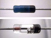
 Germanium Diode | I prefer the germanium type of diode (1 volt) because it uses the least amount of power and saves resources. They are available in many sizes and color, but all work the same. The diode acts as a "check valve" allowing voltage to flow only one direction. This prevents back flow, and ensures proper input of power. |
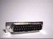 Male Connector 25 pin (printer) | The gamepad will plug into your printer port. You will need a 25 pin male connector. |
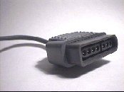 Super Nintendo Extension Cord | If you are fortunate to find an
old Super Nintendo extension cord, then you are in good shape! These can be found in
thrift stores, yard sales, used video game stores, etc.. Get as many as you can for
later projects. . If you do not have an extension cord then click here. |
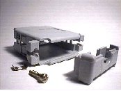 Multipurpose Hood | You will need a multipurpose hood, designed to hold the 25 pin connector. This style is great to use because you can fit all of your diodes and wiring inside it. |
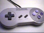 SNES Gamepad | An original Super Nintendo gamepad is highly recommended. This type uses the least amount of resources. Other Super Nintendo brands may work, but you could have complications, especially with gamepads that have lights (LEDs), extra buttons or autofire. |
Building the adapter
Click here for alternate wiring methods
Make sure you have all the parts needed for this project.
Look at the photo of the extension cord above! This shows the end that you DO NOT CUT OFF! The male end is the connector that has metal pins visible. You want to keep the male end intact with the cord. Get the extension cord and cut the off the female end. All that is left is a long cord with a male end. Carefully strip back 1-1/4" of the outer casing of the cord, exposing the five wires. Next, strip each of the five wires, 1/4" from the end.
Next, use your continuity tester to determine which wires are 1 through 7 (Note: 5 & 6 are not used). If you do not have a continuity tester, then you can probably rig together a battery, small light bulb and some wire, then test which wire is which. Use the soldering iron and coat the exposed copper wires with a thin layer of solder.
Wiring Diagram
Next, get five diodes and snip off the excess wire from each end. Make sure you leave atleast 1/4" of wire extending from each of each diode. Coat them with a thin layer of solder (don't burn the diodes!).
Now you will need to prepare the 25 pin connector. Look carefully at the connector. Each pin should have a number embossed at the plastic base. A magnifying glass will help you see this. Pins 2, 3, 5, 6, 7, 8, 9, 10, 18, and 19 will need a dab of solder on them.
You will need to solder each diode to the 25 pin connector. Make sure that the black end of each diode is NOT facing the connector. They should be opposite of the connector, ready for the extension cord wires. Get a small scrap piece of wire and coat it with solder. Snip off 1/2" piece and use it to solder the 5 diodes together, then solder wire number 1 of the extension cord to it.
Solder wires 2 and 3 from the extension cord to pins 2 and 3 of the 25 pin connector. Wire number 4 of the extension cord will need to be soldered to pin 10 on the 25 pin connector.
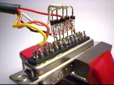
Close up view of soldering
The next thing you need to do is put everything together. If you used the same housing that is recommended in the parts list, make sure that you make a double loop in the extension cord inside the housing. This prevents dammage to the solder connections if the cord were to be tugged on.
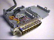 Inside View | 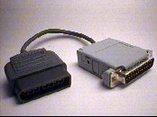 Final Product |
Testing Your Gamepad
By now, you are probably anxious to try out the gamepad. First you need to have special gamepad software drivers installed on your computer. You can download DirectPad Pro version 5.0 from here dpadpr50.zip. You will also need Windows DirectX 5.0 or better, already installed onto your computer. Get the latest version of DirectX at Microsoft DirectX.
You need a game or something to truly test the gamepad. So far, the only software that I have found that works great is at the Snes9X homepage. This program is the best SNES emulator on the web! (Don't forget to configure SNES9X for your new gamepad! You will have to assign buttons properly.)
Download this simple program to quickly test your gamepad. snestest.zip.
Visit ZELDA CLASSIC and download the game. It works perfect with the gamepad!.
You need ROMs (games) to play on the SNES9X software. Thousands of them can be found at http://www.freeroms.com/snes.htm.