
Remote
Control Encoder--PT2262
PT2262
is a remote control encoder with PT2272 utilizing CMOS Technology. It encodes
data and address pins into a serial coded waveform suitable for RF or IR
modulation. PT2262 has a maximum of 12 bits of tri-state address pins providing
up to 531,441 (or 3 ) address codes; thereby, drastically reducing and code
collision and unauthorized code scanning possibilities.
PT2262 encode the code address and data set at A0 ~
A5 and A6/D5 ~ A11/D0 into a special waveform and output is to the DOUT when TE
is pulled to "0" (low state). This waveform is fed to either the RF
modulator or the IR transmitter for transmission. The transmitted radio
frequency or infrared ray is received by the RF demodulator or IR receiver and
reshaped to the special waveform. PT 2272 is then used to decode the waveform
and set the corresponding output pin(s). Thus completing a remote control
encoding and deciding function.
The build-in oscillator circuitry of PT 2262 allows
a precision oscillator to be constructed by connecting an external resister
between OSC1 and OSC2 pins. For PT 2272 to decode correctly the received
waveform, the oscillator frequency of PT 2272 must be 2.5 ~ 8 times that of
transmitting PT 2262.
An address/data bit can be designated as bit
"0", "1" , or "f" if it is in low, high or
floating state respectively . One bit waveform consists of 2 pulse cycle has 16
oscillating time periods. For further details, refer to diagram below:
Pin
Configuration:
PT2262

PT2262-S18
PT2262-IR

|
PIN
NAME |
I/O
|
DESCRIPTION |
PIN
No. |
|
A0
~ A5 |
I
|
Code
address pin Nos. 0 ~5. These
six tri-state pins are detected by PT 2272 to determine the encoded
waveform bit 0 ~ bit 5. Each pin can be set to "0",
"1" or "f"(floating). |
1
~ 6 |
|
A6/D5
~ A11/D0 |
I
|
Code
address pin Nos. 6 ~ 11/data pin Nos. 5 ~ 0. These
six tri-state pins are detected by PT 2262 to determine the encoded
waveform bit 6 ~ bit 11. When
these pins are used as address pins, they can be set to "0",
"1" or "f"(floating). When
these pins are used as data PINS, THEY CAN BE SET ONLY TO "0" OR
"1". |
7
~ 8 12
~ 15 |
|
TE |
I
|
Transmission
enable. Active
low signal. PT 2262 outputs the encoded waveform to DOUT when this pin is
pulled to low. |
16 |
|
OSC1 |
I
|
Oscillator
pin No. 1. A
resistor connected between OSC1 and OSC2 determine the fundamental
frequency of PT 2272. |
17 |
|
OSC2 |
O
|
Oscillator
pin No. 2. A
resistor connected between OSC1 and OSC2 determine the fundamental
frequency of PT 2272. |
18 |
|
DOUT |
O
|
Data
output pin. The
encoded waveform is serially output to this pin. When PT 2262 is not
transmitting, DOUT outputs low (Vss) voltage. |
19 |
|
Vcc |
|
Positive
power supply |
20 |
|
Vss |
|
Negative
power supply |
9 |
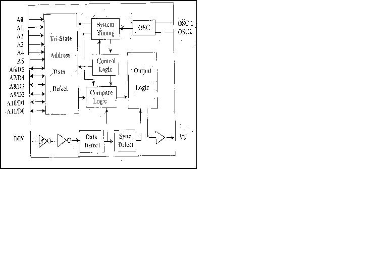
PT 2272 is a remote control decoder paired with PT
2262 utilizing CMOS technology. It has a maximum of 12 bits of tri-state address
pins providing up to 531,441 address codes; thereby drastically reducing any
code collision and unauthorized code scanning possibilities. PT 2272 is
available in several options to suit every application needs: variable number of
data output pins, latch or momentary output type.
PT 2272 decodes the waveform received and fed into
the DIN pin. The waveform is decoded into code word that contains the address,
data and sync bits. The decoded address bits are compared with the address set
at the address input pins. If both addresses match for 2 consecutive code words,
PT 2272 drives:
The build-in oscillator circuitry of PT 22272
allows a Precision oscillator to be constructed with only an external resistor.
For the PT 2272 to decode correctly the waveform that was received, the
oscillator frequency of PT 2272 must be 2.5 ~ 8 times that of the transmitting
PT 2262.
An address/data bit can be designed as bit "0", "1" or "f" if it is in low, high or floating state respectively. One bit waveform consists of 2 pulse cycles. Each pulse has 16 oscillating time periods. For further details, refer to the diagram below:

|
PIN
NAME |
I/O
|
DESCRIPTION |
PIN
No. |
|
A0
~ A5 |
I
|
Code
address pin Nos. 0 ~5. These
six tri-state pins are detected by PT 2272 to determine the encoded
waveform bit 0 ~ bit 5. Each pin can be set to "0",
"1" or "f"(floating). |
1
~ 6 |
|
A6/D5
~ A11/D0 |
I/O
|
Code
address pin Nos. 6 ~ 11/data pin Nos. 5 ~ 0. These
six pins are use as higher address input bits or data output pins
depending on the version(type) of PT 2272 used. When
used as address inputs, these pins are tri-state input pins and each pin
can be set to "0", "1" or "f". When
used as output pins, these pins are driven to Vcc if
|
7
~ 8 12
~ 15 |
|
DIN |
I
|
Data
Input pin. The
encoded waveform received is serially fed to PT 2272 at this pin. |
16 |
|
OSC1 |
I
|
Oscillator
pin No. 1. A
resistor connected between OSC1 and OSC2 determine the fundamental
frequency of PT 2272. |
17 |
|
OSC2 |
O
|
Oscillator
pin No. 2. A
resistor connected between OSC1 and OSC2 determine the fundamental
frequency of PT 2272. |
18 |
|
VT |
O
|
Valid
transmission. Active
high signal. VT in high state signifies that PT 2272 receives valid
transmission waveform. |
19 |
|
Vcc |
|
Positive
power supply |
20 |
|
Vss |
|
Negative
power supply |
9 |
Features:
Ø
CMOS Technology
Ø
Low
Power Consumption
Ø
Very
High Noise Immunity
Ø
Up
to 6 Data Pins
Ø
Wide
Range of Operating Voltage: Vcc= 4 ~ 15 Volts
Ø
Single
Resistor Oscillator
Ø
Latch
or Momentary Output Type
Ø
Available
in DIP and SO Package
Applications:
Ø
Car Security System
Ø
Garage
Door Controller
Ø
Remote
Control Fan
Ø
Home
Security/ Automation System
Ø
Remote
Control Toys
Ø
Remote
Control for Industrial Use