 |
|
|
|
|
|
|
|
|
|
|
|
|
|
|
|
|
|
|
|
|
|
|
|
|
|
|
|
|
|
|
|
|
|
|
|
|
|
|
|
|
|
|
|
|
|
|
|
|
|
|
|
|
|
|
|
|
|
|
|
|
Helpful Installation Tips |
|
|
|
 |
|
 |
|
 |
|
 |
|
 |
|
 |
|
|
|
 |
|
|
|
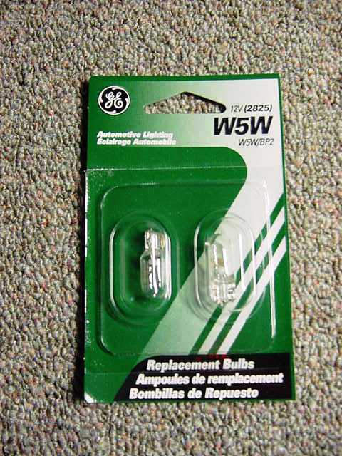
One thing that I do suggest is the use of brighter light bulbs inside the cluster. The factory bulbs are a model 194. There is a nother bulb that looks the same and is twice as bright. These are denoted with a part number of W5W (2825). These are available at Wal-Mart or any auto parts store. You will need 5 bulbs.
After doing a little research, the one of the specific uses for that bulb is the Front Side Marker Light for a 2002 BMW 325. That way you can search for it by application, if necessary.
Another suggestion for those of you with pre-1997 Thunderbird and Cougar models is to add a light bulb to the top of the speedometer to eliminate the dark spot that is created by the speedometer mechanism. |
|
|
|
 |
|
|
|
|
|
 |
|
|
Here is a step by step guide to building and assembly that will help to eliminate the dark spot from the top of the speedometer.
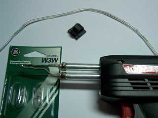
The supplies that are needed are shown in the photo at right. Two light bulbs are required, I suggest bulbs like the original factory bulbs. Those are #194, but if you can't find those, the W3W bulbs are the same. A short length of wire (about 6") and a self adhesive cable clip that I found in the automotive section at Wal-Mart.
Not shown in this photo is the electrical tape and a zip tie.
A little bit of soldering skill is required, but it's pretty easy. |
|
|
|
|
|
|
 |
|
|
|
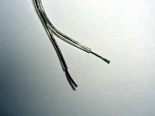
First Step: Separate the wires and strip about 1/2" of the insulation on both ends of the wire.
The wire doesn't have to be anything special. I just use speaker wire. |
|
|
|
|
|
 |
|
|
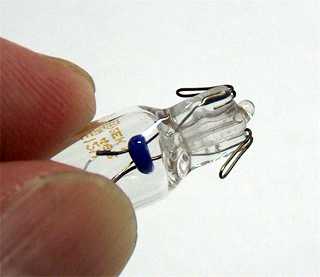
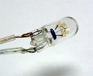
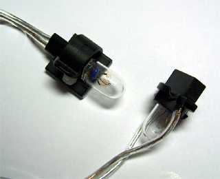
Step 2: Pull the electrical contacts on both bulbs away from the glass. You can see that the contacts are nothing more than loops of solid wire. This will allow you to feed the wire through the loops as shown in the next photos.
We will be wiring the two bulbs up in parallel. |
|
|
|
|
|
|
 |
|
|
|
 |
|
|
|
|
|
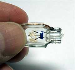
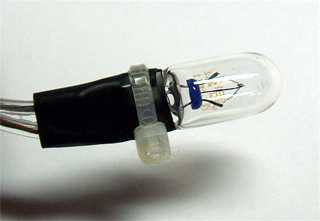
Note how the wires are oriented on this bulb. This is the one that will plug into the socket. |
|
|
|
|
|
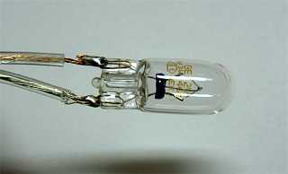
Step 3: Profit! No, just kidding. Sorry I had a little South Park flasback to the Underwear Gnomes.
Now this is where your soldering skills will come into play. Carefully solder the wire to the contacts on each of the bulbs. |
|
|
|
 |
|
|
 |
|
|
|
|
|
|
 |
|
|
|
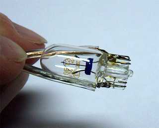
Step 4: Insulate the soldered connection with electrical tape. I like to use a zip tie to keep the electrical tape in place, but that's just me. |
|
|
|
 |
|
|
Step 5: Now it's time to assemble your newly manufactured assembly. This is what it should look like when finished. The bulb on the right is the one that plugs into the existing socket. I just have the bulb in the socket, so that you can see how the wires are routed. |
|
|
|
|
|
|
 |
|
|
|
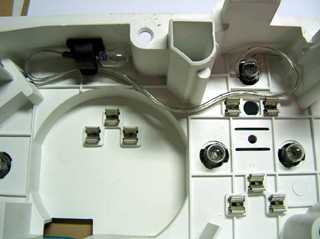
Here is a picture of the extra light assembly installed. Just route the wires so that they don't interfere with the installation of the gauges. |
|
|
|
|
|
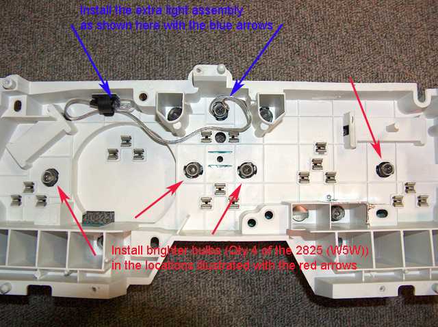
All in all, I have found that the best lighting scenario is to have the brighter 2825 bulbs installed on each side of the large gauges (shown with the red arrows) and then install the extra light assembly as indicated with the blue arrow. |
|
|
|
 |
|
|
|
Back to Gauges Home |
|
Gauge Installation Instructions |
|