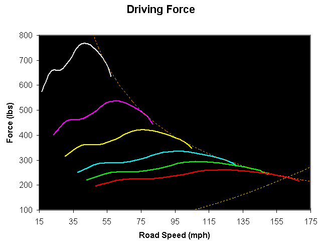
Power output from a motor is interesting data, but your bike's acceleration is going to depend on its weight and how much force it's generating at the contact patch. Drive force diagrams tell you how much force you are applying to the road, and they let you evaluate the effects of changing internal and final gear ratios, wheel sizes, even aerodynamics. You can also find optimum shift points from them, and predict wheelspin or wheelie "problems" that may limit your acceleration.
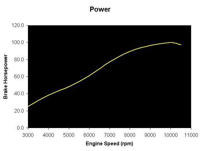
The starting point for a drive force diagram is a power measurement. While it's true that torque is the real work you can feel, torque is scaled up and down on it's path from the crankshaft through the primary gears, the transmission, the final drive and rear wheel. At each point leverage is applied, frictional losses occur. A simple method of dealing with these losses is to measure power at the rear wheel, and assume power was conserved back from the engine. Calculations at the crankshaft from this data will be in error, but calculations at the rear wheel (where the accelerating force is applied) will be correct.
| A rear wheel horsepower measurement (smoothed). This is from a calibrated Factory eddy-current dyno. If you use a dyno that estimates frictional losses, or applies generic inertial loads to the rear wheel, you may get good bragging numbers but you won't have an accurate drive force diagram |
|
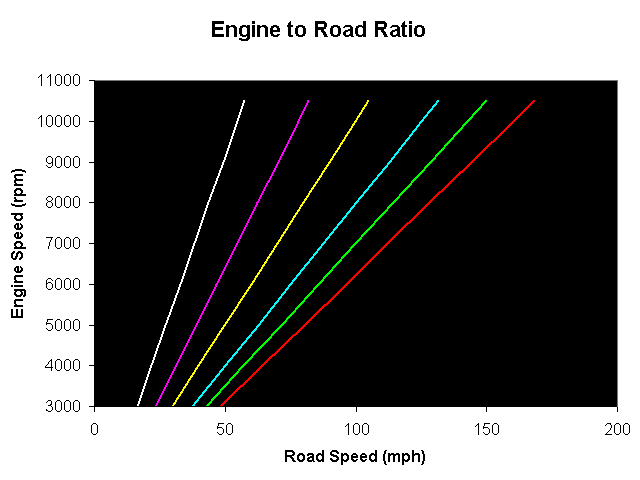
To make a useful chart, the axis has to be in road speed (MPH), not RPM. You can calculate road speed from engine speed knowing all the reduction ratios (primary, transmission, final), and knowing the rolling radius of the rear tire. I used a program to derive the diameter of the rear tire from the metric size (P180/55-17), and then tweaked the number a little until the rpm/mph function agreed with my measured data of 100 mph (indicated) at 6000 rpm (indicated), and the dyno data of 173 mph at 10,500 rpm in sixth gear. There's a 1% difference in radius between a new and fully worn tire, so don't worry too much about this.
| Data for Aprilia SL-1000 Falco | ||
| Primary ratio | 60/31 | |
| 1st gear ratio | 35/14 | |
| 2nd gear ratio | 28/16 | |
| 3rd gear ratio | 26/19 | |
| 4th gear ratio | 24/22 | |
| 5th gear ratio | 22/23 | |
| 6th gear ratio | 23/27 | |
| Final ratio | 42/16* | |
| Tire Rolling radius | 12.4 in | |
|
*stock final ratio is 41/16 in USA
|
||
|
You can calculate road speed from engine speed, knowing all the reduction ratios (then converting rpm of the circumference of the rear tire to linear miles per hour). You can use dyno data taken with a MPH axis (if was taken in only one gear!), but it's a pain because you need to multiply all your forces by the ratio of desired gear reduction to dyno gear reduction. |
Once you have the reductions figured out, you can build a table of speeds for each rpm sampled, for each gear. These speeds become the independent axis in the final plots. Calculating drive force is trickier. You need to convert measured power to torque at the rear wheel in each gear reduction . One way to start is by calculating torque at the engine (from the first graph), then applying the product of all the reduction ratios. This will give you torque at the rear wheel. Apply that torque (ft-lbs) through the radius of the rear tire (ft), and you have force (lbs) at the contact patch.
| A completed drive-force diagram. Plotting the table of contact patch forces in each gear at the each rpm, vs the road speed in that gear at that rpm, generates this family of curves. |
|
Continue to more drive force discussion?
or
Go back to the Falco home page.