|
|
|
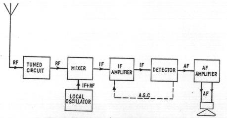
The Superheterodyne Reciver It is assumed that the reader has basic knowledge of concepts such as modulation and carriers as well as basic electronic circuits. In cases where two strong signals are located relatively closely in the frequency spectrum, these circuits will be unable to acceptably isolate the signals. To obtain the required selectivity (or Q factor), these circuits require input stages with second or third order filters. Unfortunately, these multiple stage filters can be very difficult tune into the desired frequency. The design of the Superheterodyne receiver uses a different approach that has eliminated the need for complex adjustment of the filter. The Superheterodyne uses a fixed filter and attempts to alter the desired input signal to the tuned frequency of the filter. Consider the block diagram in Figure Below.
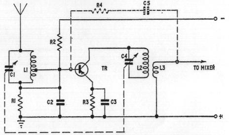
The original broadcast RF signal is picked up by the antenna and selected by a relatively broadband RF filter. This signal is usually amplified before entering the mixer. The mixer then combines the incoming RF signal and the local oscillator signal to shift the input signal to a lower frequency. The mixer thus receives two RF signals - one at the true RF, direct from the tuned circuit, and one at RF plus an intermediate frequency (IF), direct from the local oscillator. The result of mixing the two is to extract the difference or beat frequency. This is the IF frequency which now contains the AF components of the original RF signal. The signal is then passed through a multiple stage fixed filter tuned at 455kHz (which corresponds to the intermediate frequency). The filter has a bandwidth of 10kHz, which matches the bandwidth of each radio station. The IF signal is then amplified and subsequently passed through an envelope detector before AF amplification. The block diagram also shows feedback from the detector to the IF amplifier, denoted as AGC or Automatic Gain Control. This provides automatic regulation of the gain of the receiver in inverse proportion to the signal strength. This tends to keep the output level constant regardless of the input signal level. This eliminates much of the need to readjust the volume control when changing radio stations. The Figure Below shows the front end of a simple Superheterodyne circuit which provides RF amplification. Linking the RF amplifier to the tuned circuit as shown in the diagram can imply a loading on the tuned circuit, which could reduce its sensitivity. This can be avoided by coupling the RF amplifier to the mixer via a RF step-down transformer.
In many modern Superheterodyne circuits, the local oscillator and mixer are commonly combined to form a self-oscillating mixer. This has reduced the number of components required while improving the circuits stability. While considerably more complicated then any other design the Superheterodyne does offer several advantages. The IF filters can be made with very high Q factors (sensitivity) which greatly improves station discrimination and ease of tuning. In addition, the other designs all use RF amplifiers prior to demodulation. High gains from these RF amplifiers are difficult due to the high frequencies involved. The IF signal however is at a lower frequency, allowing higher gains to be achieved. These factors combine to provide performance which is generally superior to any other type of AM receiver. |

This page is maintained by Sameer Khushal.