DIGITAL VIDEO BROADCAST
INTRODUCTION
The broadcast of compressed digital TV (DCTV) signal using the MPEG-2 standard is addressed in a group of standards called Digital Video Broadcast (DVB). This group of standards was created under the supervision of European telecommunication standards institute (ETSI). ETSI adopted 10 different standards related to the transmission of MPEG-2 signals using different media. The requirements for the transmission of the signals via satellite, cable, terrestrial VHF/UHF, and microwave above and below 10 GHz are described in the DVB standards. The most relevant are briefly described below.
DVB-S
Framing structure, channel coding and modulation for 11/12 GHZ satellites service (ETS 3000 421).
DVB-C
Framing structure, channel coding and modulation for cable system (ETS 3000 429).
DVB-Data
DVB specification for data broadcasting (ETS 301 192).
DVB-CA
Support for use of scrambling and conditional Access (CA) within digital broadcasting systems. (ETR 289).
DVB-DSNG
User’s guidelines for digital Satellite Newsgathering (DSNG) and other contribution applications via satellite.
These standards are pertinent to us because they define how the MPES-2 signal will be interfaced with the satellite channel and define how to use the MPEG-2/DVB system as a platform to support applications like internet distribution.
Why
compression is needed?
In the last two decades, the telecommunication world around us has changed from analog to digital. Like many other technologies, television has rapidly gone, digital due to tremendous benefit that digital technologies provides to the broadcasters and to the viewers.
Digital compression plays a critical role in allowing television to become an interactive media by reducing the remedies amount of data involved in Transmission. As a result, new application like Direct to home (DTH), paper view, Internet TV, Low cost videoconference etc. has been developed.
Before the development of compression the conversion of a video signal from analog to digital composed of a raw rate of 298 MBites/ sec
For example.
Television picture with 576 lines and 720 pixels/line
= 414720 pixel/frame
X 30 frame/sec = 12 million pixels/sec
X 24 bits/pixel=298 Mbps.
The difficulty of moving and storing information at such higher data rates is easy to understand. For instant a typical 100 minute uncompressed move would require 210 Giga Bytes. Which could be inconvenience to store even in the largest hard drive available nowadays. Similarly it is impossible to replay the moive because even CD-ROM have only transfer rates of 1.5 Mbps and also to broadcast via satellite because even entire transponder has not more than 45 Mbps .
Hence, before use of digital TV signal, the signal must be compressed in a practical manner so that it could be broadcast easily. For such compression, the most widely used compression technique is MPEG-2 compression technique and recommended by ITU (ITU-T Recommendation H.222 for system and ITU-T Recommendation H.262 for videos.)
MPEG-2 (Motion Picture Expert Group – 2)
MPEG-2 deals with encoding (compressing) of interlaced video of NTSC, PAL or High definition Television (HDTV) signals. It is intended to operate primarily in the 2 to 15 MBPS range and to be used by television, HDTV, Digital Video Disk, Video Storage on CD-ROM, Video conferencing etc. Every application has a different requirement in terms of processing delays, scalability and resilience to error.
Compressed TV Channel Data Rate (Using MPEG-2)
The selection of a particular TV information rate depends on two factor.
i) Type of service.
The services can range from newcast and moves to full motion sports shows as described. in below given table-1
ii) Service Quality:
Quality in digitally compressed TV Signal does not entirely depends on the link C/N, but on the data rate selected and the quality of the transmission link determined by the EB/NO at the receiver. The Higher the program data rate the better the quality.
|
Application |
Suggested compressed TV Data rates (Mbps) |
|
Films and Broadcasts |
3.5 |
|
Live sports |
4.6 |
|
Studio quality signal |
8 |
|
Audio |
0.128 (Mono) 0.256 (Stereo) |
The final rate for a specific channel will be the addition of the rates of TV, Audio and control information.
Carrier Operating Modes
The broadcast of compressed TV signals can be achieved by means of two different transmission modes, multichannel per carrier (MCPC), and single channel per carrier (SCPC). MPEG-2 allows both modes and the equipment in both cases consist of encoders and multiplexer. For SCPC the encoder is only one.
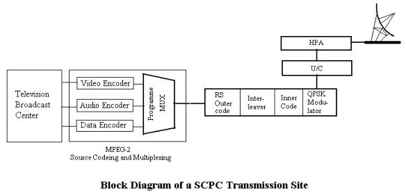
SCPC Operation
In SCPC, every TV channel uses one digital carrier. Therefore, the carrier does not fill the entire transponder and the transponder's bandwidth is shared among different carriers. This multi carrier operation in the transponder will require the application of an output power back off to reduce the effects of intermodulation products.
MCPC Operation
MCPC operation provides great flexibility to the broadcaster because one carrier can accommodate several TV channels. The user has the ability to independently select the rate in each MPEG-2 channel encoder, and the MPEG-2 system multiplexer will combine the PES from different channels into a fixed-rate stream according the satellite transponder capacity.
As a result, one MCPC carrier can convey a combination of several channels (sports, movies, news, etc.). The number of channels in a carrier will depend on the individual rate assigned to each channel.
Table 8 contains a comparison between MCPC and SCPC. Comparison between MCPC and SCPC
|
SCPC Advantages |
SCPC Drawbacks |
MCPC Advantages |
MCPC Drawbacks |
|
Lower per carrier data rate leading to lower e.i.r.p |
Larger HPA backoff to Accommodate several Carriers. |
Avoiding the waste of power caused by the transponder backoff |
high data rates |
|
Able to operate in fractions of a transponder |
The transponder can Not be used at saturation. |
More power available from the satellite to minimize the receiver dish size |
Usually it needs a full Transponder |
|
Good for SNG Applications |
Each channel will Require an individual Data and control Channel. |
Efficient use of the satellite capacity which means more TV channels per transponder |
|
|
|
Each Channel will Require its own system Multiplexer to create The TS thus making it more expensive to operate. |
Generally lower equipment costs |
|
|
|
|
Good for DTH applications |
|
|
|
|
Able to carry internet traffic |
|
Space
Segment requirements.
The amount of satellite resources (bandwidth , power) to use depends on the size of the receiving antenna, type of forward error correction used, operating modes, location of the antenna within uplink and downlink satellite footprint (Known as pattern advantages), the carrier information rate and the service availability target.
Antenna Gain, G dbi = 10log(n) + 20lof(f) + 20log(d) + 20.4 dB
n = antenna efficiency
d = antenna diameter
f = operating frequency
Bandwidth =symbol rate * 35 %RCRO
Symbol rate = Interface Rate * Framing rate x 1/RSCode rate x 1/FEC rate x modulation factor
Receive signal = EIRPDown – path loss
DVB for internet
The System multiplexer in MPEG-2 operates as a packet multiplexer. This feature allows the same TS to be able to transport all kinds of data, provided that they are properly packed. Originally, the TS was intended for the distribution of video and audio for broadcasting purpose. However, considering the fact that other applications like data broadcasting, software download, interactive TV and internet services can benefit with the broadcast compatibilities on MPEG-2 via satellite. ETSI introduced the standard ETS 301192 (DVB for data broadcasting ). This standard defines the requirements to use the same MPEG-2 system multiplexer and the same TS data rate to convey additional data traffic.
Summary of advantages of MPEG-2/DVB
Finally, a brief list of advantages of MPEG-2/DVB systems could include:
-
The video quality remains the same throughout the network. No snow, no artifacts, no degradation, as long as the C/N is above the threshold.
-
Encryption and conditional access keys designed for truly anti-piracy protection
-
Fully flexibility in terms of bit rates and number of channels per carrier
-
More channels per transponder.
-
As widely accepted MPEG-2 form, any digital IRD boxes can be used to view the TV channel.
-
Same system can be used for Internet distribution, hence allow multicast services through same capital investment.