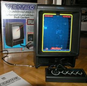
Das Vectrex ist eine Spielkonsole, die 1982 auf den Markt kam. Auff�lligstes Merkmal ist der eingebaute Hochformat-S/W-Bildschirm zur Ausgabe der Vektorgrafik. Dieser Kompaktaufbau f�hrte zur Einstufung durch Fachzeitschriften in eine eigene Kategorie: Mini-Arcade. Federf�hrender Entwickler war Jay Smith, welcher bereits 1979 das Microvision Handheld f�r MB entwarf. Hergestellt und ver�ffentlicht wurde die Konsole in den USA von General Consumer Electric (GCE) ab Oktober 1982. In Europa und Japan �bernahm MB den Vertrieb. 1984 stellte MB den Vertrieb ein.
Der Rechnerteil bestand aus einem mit 1,5 MHz getakteten Motorola 6809-Mikroprozessor mit 1 KB RAM und 8 KB ROM (4 KB 'Executive' und 4 KB f�r Minestorm). Als Soundchip kam ein AY-3-8912 von General Instrument zum Einsatz. Der Bildaufbau erfolgte komplett CPU- gesteuert, d.h. die CPU steuerte in Echtzeit das Zeichnen auf dem Schirm �ber eine X/Y-Ansteuerung der Bildr�hre.
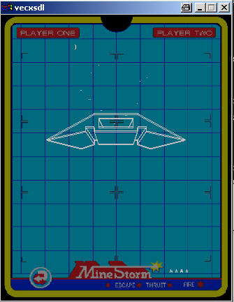
Als Emulator eignet sich MESS. Oder auch - ohne Sound - Vecx. Portabel und inkl. Sourcecode in C! L��t sich so mit mingw compilieren. (Tasten: a,s,d,f, csr-links+rechts) F�r DirectX (Ben�tigte Header zum compilieren gibts bei www.sdl.org)
Kleiner Emulator mit C Source und Mingw win32 exe: vecx.zip
6809 Assembler mit C Source und Mingw win32 exe: vec_a09.zip
Core emulator by Valavan Manohararajah. Homepage: http://www.valavan.net
SDL+Overlay code by Thomas Mathys.
Sound emulation code by James Higgs. Homepage: http://jum.pdroms.de
E-Mail von: James Higgs
Vectrex Trouble Shooting Guide (EN)
Wieviele Vectrex wurden gebaut? Wieviele gibts davon heute (2007) noch?
Diese Frage kann ich bis heute nicht wirklich beantworten. Im Usenet fand ich:
> Does anyone have any info regarding the sales figures of the vectrex?
Since it looks like the serial numbers were created serially as they
should be, you can get some idea based on collecting some serial
numbers and seeing how high each "group" goes. I have a list from long
ago that will get you started. The "groups" are based on region, i.e.
USA, Canada, Europe, etc..
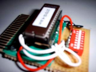
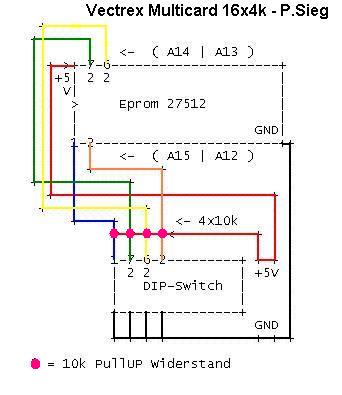
Ich habe dann einen Adapter f�r das 16x4k Eprom gebastelt, wobei A12-A15 �ber 10k Widerstand (pullup) an 5V liegen und
�ber DIP-Schalter an GND gelegt werden k�nnen. Und so sieht es aus:
Schwarz=GND, Rot=+5V, die 4 wei�en Dr�hte gehen zu A12..A15.
Also eingel�tet ist ein Pr�zisionssockel. Dann kommt ein Billigsockel, an dem PIN: 1,2,26,27 zur Seite gebogen wurden (1=A15,2=A12,26=A13,27=A14). Damit kein Kontakt zum unteren Sockel m�glich ist, mu� man die entsprechenden Kontakte am unteren Sockel z.B mit Isolierband abkleben!!
Nicht sch�n, aber es funktioniert!!
Ich habe mal versucht ein Layout der Bauteilplazierung und Verschaltung zu erstellen (Ich hatte nur ein 8-fach DIP-Switch.. 4-fach h�tte gereicht).
Dazu habe ich zuerst als ASCII Zeichnung probiert.. war mir aber zu un�bersichtlich.. Hardcopy gezogen und in Paint die Verbindungen farbig nachgezogen.. Hier das Ergebnis:
Hier das Eprom-Image: vec_27512_4.zip
I discovered a couple of inconsistencies between the schematic's part list and my machine. These caps may have originally matched the manual, and later replaced, though I can't tell for sure:
1) C507 is 47uf-100V, not 4.7uf-100V.
Once I had all my parts, I spent about four hours installing them and tightening up solder joints. I didn't see any particular joint that stood out as definitely cold, but there were some where the solder was dull. Some of the joints looked like they didn't get much solder at the factory. I remedied all of these and made all the joints on both boards nice and shiny.
One thing to note on the power board is that two of the caps I had to replace (including C409) live underneath the large heat sink in the middle. I will reiterate: The Vectrex was NOT built with service in mind. To remove this heat sink:
1) Unscrew the two screws on the top side of the sink that hold it to the IC.
While the heat sink was off, I cleaned off the old heat-sink compound and replaced the mica on the two side transistors. When I put the heat sink back on, I put some new heat-sink compound on the two transistors and the IC. It was the least I could do to make this board prettier. :)
I almost replaced the +5 and -5 voltage regulators, but decided against it. These are the two transistors on the side of the large heat sink on the power board (a 7805 and a 7905, respectively). I decided against it because I figured that these probably powered the logic board, which by all accounts was working fine.
One of the Vectrex-heads that I talked to mentioned that when he replaced the two caps under the heat sink, he put them on the BACK side of the board so that he could replace them more easily in the future. I realized that I hadn't done this when I was done swapping out parts, but I probably should have taken his advice. Oh well. The heat sink fit back on just fine, though.
After swapping out 4 caps on the logic board, 22 caps on the power board, Q502, and R529, I was ready to put the machine back together and see if it worked! Before this, though, I blew another can of cleaner/degreaser on the boards. Most of this went to the logic board, which will always be dirtier than the power board since it sits horizontally. Then I carefully put the machine back together, following my notes in reverse order.
Allow me to say it again: I'm really glad I took good notes while disassembling this beast. Other monitors are easy to pull apart, but this one is a real BITCH. Be warned.
I left the back cover off of the unit so I could watch in case anything blew up when I turned it on. At least that might give me a clue about where to look in the event of failure. I plugged it in, turned it on ... and the familiar Vectrex "da-da-dummmm" came on. I hadn't broken it! And I noticed that the background hum on the speaker was quite a bit softer. The work of new filter caps, no doubt.
I played Mine Storm for about thirty minutes before I realized that I had played Mine Storm for thirty straight minutes without the monitor going nuts. It's fixed!
The problem was therefore one (or a combination) of three things:
1) A cold solder joint with an intermittent connection. I don't think this is very likely, but possible.
And after working on somewhere between fifty and a hundred monitors, I still have only seen one bad flyback. It was on the dearest item in my game collection -- my Robotron -- and it was shooting blue sparks out of it like a Frankenstein movie.
I still need to figure out what all the adjustment pots on both boards do, because the alignment and size of some vectors suggest that there's an adjustment out of whack somewhere. If someone out there actually managed to read this far, and knows how to align the screen, could you send me an Email? I have Sean Kelly's excellent multicart, which has a great test pattern generator on it. Thanks for reading! I hope my rambling was helpful to any would-be techies out there. :)
Addendum:
In regards to "that suction cup", just make sure as hell you have discharged the tube before you go putting yourself at risk of getting a 20,000 volt shock. Not a good way to end the day, or your life.
-Jeff
This story: �2001-2007 Guddler's Domain
Symptoms: Picture seriously screwy. Lines didn't meet up at all
Well, after going to the retro ball back at the start of December, I'd been playing on a Vectrex console, was seriousy impressed and decided I wanted to get one. I tried one of the console places that was at the show (who shall not be named) and despite promising me that they had them in stock for �70, basically just completely failed to respond to my two emails I sent so I popped a wanted post out on UKVAC. Lo and behold I was offered one that was 99% working for �25 - bargain :)
The disclosed problem was that the lines didn't line up properly on all games. Apparently Minestorm was fine though. While I was waiting for the unit to arrive (not long!) I read the service manual and it honestly sounded like this was going to be nice and easy. It sounded like it had just gone out of adjustment and needed a good service - Excellent!
Well, that's about where the optimism ends! The unit turned up, and fair enough, it was as described, although I did notice that the controller didn't always want to work. I figured I'd come back to that later. So, popped it on the bench. Cut open a soccer cart, fitted a socket and adjusted the address lines to take a 2732, then burnt the test rom. Bingo - 1 test cartrdige. After going through the whole test procedure it became apparent that there was more up with this than first met the eye. I could get the lines to all meet up with hideously stretched text, OR, I could get nice looking text with terrible lines. That's a pain. I also noticed that the sound buzzed to the point where it was really unusable. So now that's 3 faults!! Hmm.
Determind to give the thing a good service as well as just fix it, I ordered in replacements for all the caps and ICs in the unit, together with most of the transistors and diodes too. Armed with this I replaced every single electrolytic cap and I also replaced the big 3A rectifier diodes too since one of my tests showed quite a lot of noise on the recitfied voltages. Unfortunately though, no improvement to our original problem.
SO, on to the logic board (oh, and what a PAIN these things are to work on!!). Wanting to never have to dismantle the thing ever again I started by socketing every damn chip in here. After that, fixing the problem was basically just a case of swapping each out until the problem was solved. However, being a little cleverer than that was not hard! The schematics showed me that frankly, the problem was probably the DAC. And it was! Thankfully replacements were easy to get hold of.
Before putting it back together I sorted the buzzing out. I implemented the two fixes detailed at PlayVectrex.com. The results are astounding. However a word of warning! This was NOT an easy thing to do!!
SO, I now have a Vectrex that doesn't buzz and looks great, however, every now and then the controller wouldn't work on startup. A friend came over and pointed out that on top of this, it didn't display the Vectrex startup screen and that often the tunes that played sounded very drunk. Having not owned one before I didn't know this, but took it on board and yet something else was up with it.
Firstly, using his known good unit we worked out that if you held a button down while powering the unit up it bypassed the startup screen. It was starting to sound like something was up with my controller inputs that may also be effecting my sounds. Odd. Looking through the schematics showed me that interestingly enough the sound chip (an AY-8-3912) also handled the inputs as well so figuring my two were related I had a dig through a box of scrap boards and found some quiz machine board with the relevent chip. Replaced it and bingo. Sorted Vectrex :o)
Parts Used:
From: Mike Blackwell
>From the Vectrex Technical Description (my comments in {curly braces}):
The HP3000 {Vectrex} is a microprocessor based, vector scan system using a
standard 9" black & white CRT as its video display device. The
microprocessor (MPU) is the Motorola 68A09 device {hardware multiply and
divide!}. The MPU operates at 1.6 MHz from a 6 MHz extrenal Xtal. An
internal divide by 4 circuit generates the MPU 1.6 MHz "E" clock signal used
in the system. Program memory is stored in the 8K x 8 2363 {really 2764}
type ROM. This ROM contains common subroutines, the "executive" or assembler
instructions plus one complete game {Mine Storm}.
Two 1K x 4 2114 type static RAMS provide storage locations for data
indicative of locations of objects, game status, and various other
information needed by the microprocessor during game operation. Peripheral
Interface Adaptor (PIA) Chip {a 6522A}, has two 8 bit peripheral ports which
interfaces the MPU with peripheral devices and external signals. One of the
PIA ports interfaces the General Instruments AY-3-8912 sound-IO chip with
the MPU and also drives the digital to analog converter chip MC1408. The
other PIA port is used as control lines for the sound chip, selector control
for the multiplex chip and as means to read the A/D comparator that's used
in the joystick successive approximation circuitry. Sound is either MPU
generated directly or by use of the AY-3-8912 sound chip.
The AY-3-8912 sound chip is a programmable sound generator containing 3 tone
generators and wave shapping circuitry. This chip also has a single 8 bit IO
port used to read the status of each of the handcontrollers 4 action
switches.
The standard TTL device types 74LS00 and 74LS32 are usued as control line
decoders to allow the MPU to select the appropriate circuit element to be
addressed at any particular time.
The analog processing section includes digital to analog converter (DAC)
chip type MC1408, dual 4 channel multiplexer/demultiplexer chip type CD4052,
and dual op-amps types LF353 and LF347.
DAC chip M1408 receives an 8 bit word at data terminals D0-D7. DAC output
(pin 4) is current source. One section of IC LF353 is used to change this
current to a voltage representative of the 8 bit digital word received by
the DAC chip. The LF353 voltage is applied to an input of the dual 4 channel
multiplexer (MUX) chip CD4052. This same voltage (designated "DAC" on the
schematic) is the X-axis drive signal.
The CD4052 MUX chip serves two purposes: it selectively couples, under MPU
control, the output of the DAC current/voltage converter to one of 4 places
and is used to selectively couple the inputs from the joystick pots to the
voltage comparator IC LF353.
The 4 places to which the "DAC" signal is coupled by the MUX are:
1) The Y-axis sample and hold IC LF347
Each of these 4 signals is a voltage value representative of the 8 bit DAC
input word for that function.
The joystick pot positions are sensed by a successive approximation process.
The MUX chip selects each joystick pot input line and applies it to the plus
input of comparator IC LF353. At the same time the MPU generates digital
words that are changed to voltages by the DAC and current/voltage converter
mentioned previously. These voltages are successfully {successively} applied
to the comparator's minus input until the MPU generated voltage is equal to
the joystick voltage. The MPU then recognizes the digital word
representative of the comparison voltage and is able to establish a location
for the joystick pot. The present position for each joystick is sensed in
this manner. The pot position information is updated on a regular basis by
the MPU.
Returning to the X and Y axis drive signals, these signals are applied to
X,Y integrator IC LF347 negative input pins through series analog switch
types 4066B. The "zero" reference signal is applied to the positive inputs
of the integrators. There are also analog switches across integrator IC
capacitors. The series analog switches are controlled by MPU signal RAMP and
the parallel capacitor switches are controlled by MPU signal Zero 10. RAMP
10 determines when and for how long the X and Y axis voltage levels will be
applied to the integrator amps. Zero 10 is used to discharge the X & Y axis
integrator caps thus initializing them for the next signal to be integrated.
The outputs of the X,Y axis integrators are coupled through J-FET switches
to IC LM379 deflection amplifiers. The LM379 operates as a voltage to
current driver, the current through the deflection coils forming the
electromagnetic field which deflects the CRT beam. To protect the CRT from
spot burn in the event of a loss of deflection, the Y axis drive amplifiers
output is detected and a deflection enable/disable signal is generated. This
signal controls the J-FET switches in series with the X,Y deflection amp
inputs to reduce the scan drive signal in the event of a software or
hardware failure plus discrete transistor type 2SC1921 operates to bias off
the CRT.
Conventional full wave rectification and three terminal regulators are used
in the low voltage power supply. A special negative DC source is generated
by a voltage double-circuit which is used to supply a 13V to the DAV chip.
The high voltage is generated via an oscillator, drive transistor and
flyback type transformer circuitry similar to what is commonly used in small
black and white TV receivecrs.
Judicious use of bypass caps, RF filter chokes, ferrite beads, etc., has
been used in the design to control RFI emmisions.
Dokumente zum Thema (EN):
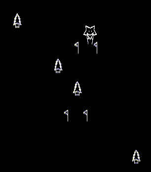
; this game was written on 08.02.1998 by christopher salomon
; *** Spike goes Skiing ***
Hi Peter

I'm glad it worked so easily. I think this is mostly
due to how vecx was originally written to work
cross-platform.

I don't mind if you release your version of vecxsdl on
your site.

My code can be GPL, however I don't know what the
other authors want for their code.

Regards,

James Higgs
Vectrex Service Manual (EN)
Links:
http://www.vectrexnews.com
http://www.vectrex.nl
http://www.pelikonepeijoonit.net/vec/index.html
http://www.playvectrex.com/designit/chrissalo/toc.htm
http://www.vectrex.biz/
http://geovector.tripod.com/_sgg/f10000.htm
http://www.valavan.net/vectrex.html
http://mitglied.lycos.de/vectrex/start.htm
http://www.emix8.org/static.php?page=VectrexThrustSource
http://www.madtronix.com/html/vectrex.html
ftp://ftp.csus.edu/pub/vectrex/
Units sold
Here's my list:
---------------
GCE Vectrex Units
MO: HP3000 (USA)
0000001
0010627
...

0025575
0029907
0039282
...

0092498
0094206
...

0146020
0146795
0149956

ODD ONEs
133905A
139549A

("looks like these are consistently increasing. Maybe there where only
150,000 HP3000's produced. We'll have to see how high it gets.")

GCE Vectrex Units
MO: 3000-CI (Canadian Units)
1012059
1012980
....

1023435
1024993

MB Vectrex Units
MO: 3000 UI-U.K.
2016726
2023309
2028604

MB Vectrex Units (Germany)
MO: 3000-GI-EURO
(EUROPEAN MB)
Old ROM
3010206
3013344
3019282
3037558
New ROM
3061304
3063733
...

3086194
3090492
3116019

Other MB Vectrex Units
4012812
4018788

Notice the 1,2,3 beginning #'s for the MB EUROPEAN units. It looks like
there may have been 5 different starting #'s 0000000, 1000000, 2000000,
3000000, & 4000000.

Anyone have serials from the Japanese Vectre-i (I forgot how we were
doing the plural Vectrex word - yes that has been debated as well ;) )?

Sincerely,
Brett Walach
http://www.PlayVectrex.com


Daraus schlie�e ich:
Es wurden NICHT 4 Mio. St�ck zw. Oktober 1982 und Mitte 1984 gebaut!
Es gab 4 Seriennummerngruppen:

0 xxx xxx   GCE Vectrex Units MO: HP3000 (USA)
1 xxx xxx   GCE Vectrex UnitsMO: 3000-CI (Canadian Units)
2 xxx xxx   MB Vectrex Units MO: 3000 UI-U.K.
3 xxx xxx   MB Vectrex Units MO: 3000-GI-EURO (EUROPEAN MB)
4 xxx xxx   MB Vectrex Units Other

Innerhalb eines jeden Bereichs sind die Seriennummern fortlaufend.
Anhand der 'h�chsten' Seriennummern in jedem Bereich kann man die Anzahl der Units pro Bereich ermitteln. Die Summe aller Bereiche ergibt dann die Anzahl aller Units.

0 -  200000
1 -   25000
2 -   35000
3 -  100000
4 -   25000
Daraus erg�be sich eine Gesamtzahl produzierter Ger�te von ca. 400.000 St�ck.

Wenn wir annehmen, das davon noch 10% bis heute (2007) �berlebt haben, so kommen wir auf ca. 40.000 St�ck.
Meine Multicard
Hier beschreibe ich meine Versuche, eine sog. Multicard zu bauen.
Als einziges Modul zum 'schlachten' hatte ich Blitz (8k).
Zun �ffnen einfach die Schraube an der Unterseite l�sen und die Plastiknasen/-haken an der Einschubseite l�sen.
Ich wollte zuerst das ROM sauber ausl�ten. Hatte schon entsprechende Erfahrung mit dem Ausl�ten von IC's beim C64 gesammelt. Aber ich hatte nichts, um diese kleine Platine vern�nftig zu fixieren.. so gings gar nicht.
Also habe ich mich kurzer Hand entschieden, die PIN's nah an der Platine
abzukneifen und einen passenden Sockel einfach aufzul�ten. Dabei immer wieder kontrollieren, das alles korrekt verbunden ist!
Es sollen 16 x 4k Programmbereiche �ber 4 Steckbr�cken/Schalter w�hlbar sein.
Cartridge slot Belegung:


  OBEN               UNTEN
 -------           --------
   2. Vcc (+5v)    1. /HALT
   4. Vcc (+5v)    3. A7
   6. A8           5. A6
   8. A9           7. A5
  10. A11          9. A4
  12. /OE (1)     11. A3
  14. A10         13. A2
  16. /CE (2)     15. A1
  18. D7          17. A0
  20. D6          19. D0
  22. D5          21. D1
  24. D4          23. D2
  26. D3          25. GND
  28. GND         27. GND
  30. R/*W (3)    29. A12
  32. /CART(4)    31. A13
  34. /NMI        33. A14
  36. /IRQ        35. (5)


(1) Inverted copy of 'E' clock from CPU. Valid CPU access when E is high
(2) A15 from CPU according to the nut. ;) However, the commercial carts I've seen use this line for chip enable.
(3) Note: unused on many carts
(4) Active low Cartridge enable - low when E is high and A15 low. Although I verified that it seems to work, many carts do not use it.
(5) Port B, Bit 6 of the 6522 PIA (software controlled line)

Hier ein 2764 (8k) Eprom und ein 27512 (64k) Eprom im Vergleich:


    +-------\/-------+            +-------\/-------+
 1 -|Vpp          Vcc|- 28     1 -|A15          Vcc|- 28
 2 -|A12         /pgm|- 27     2 -|A12          A14|- 27
 3 -|A7            nc|- 26     3 -|A7           A13|- 26
 4 -|A6            A8|- 25     4 -|A6            A8|- 25
 5 -|A5    2764    A9|- 24     5 -|A5   27512    A9|- 24
 6 -|A4           A11|- 23     6 -|A4           A11|- 23
 7 -|A3           /OE|- 22     7 -|A3       /OE-Vpp|- 22
 8 -|A2           A10|- 21     8 -|A2           A10|- 21
 9 -|A1           /CE|- 20     9 -|A1      /CE-/PGM|- 20
10 -|A0            D7|- 19    10 -|A0            D7|- 19
11 -|D0            D6|- 18    11 -|D0            D6|- 18
12 -|D1            D5|- 17    12 -|D1            D5|- 17
13 -|D2            D4|- 16    13 -|D2            D4|- 16
14 -|GND           D3|- 15    14 -|GND           D3|- 15
    +----------------+            +----------------+


Und hier der 'Plan' der Umschaltung:

Connect pin 26, 27 and 1 (A12, A13, A14, A15) via pullup resistor of 10k and switch to GND for address range selection
of the 16 x 4k blocks:

   o------+-----+ \-----| GND
  26      |    switch
  27     +-+
   1     | | 10k
         +-+
          |
          +  Vcc

Nun wie es aussieht, kann man ein 27512 einfach auch direkt einstecken, wobei dann nur ein 4k Block aktiv ist
(wahrscheinlich der obere).

16x 4kb Spiele:

AAAA<- Adressleitungen
1111
5432
0000 - armor
0001 - bedlam
0010 - berzerk
0011 - castle
0100 - chasm
0101 - hyper
0110 - mstorm2
0111 - ripoff
1000 - rocks
1001 - space
1010 - starhawk
1011 - sweep
1100 - vpong
1101 - ski
1110 - philo
1111 - castle


Nun, es war nicht ganz wie erwartet.. A12+A15 scheinen auf 0V zu sein.
16x4k = mstorm2 wird gestartet und l�uft!

Also sind:
AAAA
1111
5432
0110 - Pegel verdrahtet.
Joystick Reinigung
Vectrex_Joystick_Reparatur.pdf
Joystick Umbau f�r Vectrex
The Sega Genesis Controller is a digital controller. The Vectrex joystick
is an analog controller. Games like Minestorm don't look at the analog
values of the joystick and only look to see what direction the joystick is
moved. Games like Minestorm work with these converted Sega Genesis
Controllers. Games like HyperChase look at how far the joystick moves in a
direction and are not fun to play with these converted controllers.
Schematic:

Direction Control:
                     +5V (Pin 7)
                      ^
                      |     10K
                   .__|__/\/\/\/\___.
                 |                  |
Right Button    -|         3.3K     |
                 | ._____/\/\/\/\___|
                                    |
                                    |
                                    |-------- X Direction
                           3.3K     |          (Pin 5)
                   ._____/\/\/\/\___|
                 |                  |
Left Button     -|                  |
                 | ._____/\/\/\/\___|
                      |    10K
                      |
                    -5V (Pin 9)


                     +5V (Pin 7)
                      ^
                      |    10K
                   .__|__/\/\/\/\___.
                 |                  |
Up Button       -|         3.3K     |
                 | ._____/\/\/\/\___|
                                    |
                                    |
                                    |-------- Y Direction
                           3.3K     |        (Pin 6)
                   ._____/\/\/\/\___|
                 |                  |
Down Button     -|                  |
                 | ._____/\/\/\/\___|
                      |    10K
                      |
                    -5V (Pin 9)


Button Schematic
                                            Same for Button B,C, and Start
                                            except:
                                                  Button B -> Pin 3
                 .__________ (Pin 2)              Button C -> Pin 4
               |                                  Button Start -> Pin 1
Button A      -|
               | .___
                     |
                     |
                    GND (Pin 8)


Pins listed are those of the 9 pin connector.

Vectrex Controller

9 PIN CONNECTOR

Pin Description

1   Button 1
2   Button 2
3   Button 3
4   Button 4
5   Horizontal Pot
6   Vertical Pot
7   +5V
8   GND
9   -5V

The joystick potentiometers work by voltage division between -5V and +5V. Actually, it uses a couple of resistors on
each side to make it more like -3.4V to 3.4V.

Vertical Pin 6:

Voltage Direction

-3.4 V  Down
0 V     Center
+3.4 V  Up


Horizontal Pin 5:

Voltage Direction

-3.4 V  Left
0 V     Center
+3.4 V  Right
Repairs
(My Vectrex Works Once Again!)
by Jason Merlo
Hello, newsgroup regulars and non-regulars alike -- I thought I might share some of the things I've learned over the last week and a half while attempting to repair my Vectrex machine. I'm not an expert in electronics, but I know a few things and this is one of those occasions where I actually diagnosed the problem correctly and fixed it! If you're a seasoned repair tech, this message will probably bore you from here on out and you'll wince at some of my terminology. But if you're like me and enjoy tinkering, you may also enjoy my notes below.
First of all, my machine is a Japanese Bandai Vectrex. It has Japanese writing on all of the console and controller decals. I don't know if it's any different internally from the American Vectrex, since the schematics I have seemed to match up pretty close. Exceptions are noted below.
The symptoms: The monitor on this machine used to work just fine with a nice picture until a couple of years ago. Then suddenly, the machine would work upon power-up for about five minutes, and then the monitor would go crazy, with vectors jumping around and everything. Shortly after this, The picture would fade out slowly. As the picture faded out, the image would increase in size -- sort of a 'zoom in, fade out', if you will. After taking the back cover off of the Vectrex the first time, I noticed that the tube filament (the orange glow you see in the neck of the tube) would fade out along with screen. After this the monitor would be dead until you turned it off and on again. The longer you waited with the power off, the longer the picture would stay stable before flipping out the next time. During monitor freak-out periods, the game itself would play fine, as evident from the game sounds I was still hearing.
My first thought: Oh shit, it's the flyback transformer. Probably completely irreplaceable in a unit this old and this obscure. A nine-inch vector monitor isn't exactly state of the art anymore. Not that it was to begin with. :)
My second thought: The monitor DOES work for a short time, and in my experience when flybacks go, they GO. So something must be overheating. I took the machine apart and blew an entire can of cleaner/degreaser on the board parts that I could get to. I was sure that removing the thick layer of dust from the logic board would help. But this didn't fix the problem.
My third thought: This machine is NOT built for service. I spent the better part of a day figuring out how the two boards were affixed into the plastic shell. I took careful notes on which wires I had to desolder and where molex plugs went.
For the record, here's the order in which I took apart the Vectrex. There's probably easier ways to get to all the board components, but this is how I did it:
1. Turn the machine down on its face, and remove the back cover. This just lifts off. Probably the easiest part of the repair. :)
2. Unsolder the four monitor yoke wires from the power board. The power board is the vertical board in the left of the cabinet. These wires are in a small line in the center of the board and are colored blue, red, green, and yellow. The four wires loop around and attach directly to the picture tube. I do not understand why the yoke wires are not attached to a molex harness. All of the other monitors I've worked on in video games have a harness that is easily removable. I intend to go back in when I have time and install a harness. Maybe the American Vectrex is different?
3. Unsolder the three wires in the bottom front of the power board. I think these come directly from the transformer at the bottom of the console. There is one white and two red wires here. Make sure to note which red wire goes where. I put a piece of scotch tape on one of them to differentiate them. Also unsolder the short ground braid that connects the two boards.
4. Unplug all molex harnesses between the two boards and remember (or write down) where they go.
5. Clip the white wire tie that holds the neck board to the picture tube. Remove it, and then *gently* pull the neck board off of the picture tube, straight back. Be careful -- I once dropped the back door of a Phoenix machine into the cabinet and sheared the stem of the picture tube clean off. I got lucky -- the tube didn't shatter into a million pieces because it was such a clean break.
6. Get a flathead screwdriver and attach a wire to the metal part of it. Then attach the other end of the wire to something grounded. I used the metal frame of the monitor. There's not much metal inside of a Vectrex, but this seemed to work okay. Then use the screwdriver to remove the anode cap (the suction cup looking thing) off of the picture tube. It has two prongs which need to be squeezed together to unhook it. You may hear a pop when you first put the screwdriver under the rubber. This is normal -- you're discharging the picture tube.
7. Now unscrew the green ground wire from the upper left corner of the picture tube. Also unscrew the two screws holding the power board to the plastic carriage. The power board should come out completely now. Sit it aside and take out the two big screws holding the carriage to the cabinet. Sit this aside too.
8. Now the fun part. Pull the on/off knob straight off. It's hard to do, but it should come off completely. Now take out the one screw that holds the cartridge port and the logic board together. Also remove the four big screws that hold the logic board chassis to the cabinet. Two of these are above the transformer. The entire chassis should come out now and the cartridge port sheath should come off entirely. Put the picture tube in a safe place where it's not going to fall. I put mine next to my cats food and then moved it when I found out that kitty wanted to play with the Vectrex too. Bad kitty, bad!
9. I could never get the logic board completely separate from plastic, but I did get it to the point where I could solder on the rear side without melting anything important. Turn the board upside down and unsolder the two reset button wires from the bottom of the board. There is one gray and one black wire. Then turn the board back over and take out the last three screws. You should now be able to flip the board by itself over to work on it. Whew!
Things I replaced: I've installed many, many Zanen cap kits over the years, so I figured the one thing I would do for sure was replace all the electrolytic caps on both boards. There are four of them on the logic board, and 22 on the power board. After looking at the schematic and talking to a few repair-head friends, I decided that the monitor filament circuit was suspect as well. I got a couple of suggestions to replace the big heater resistor in the circuit. This is R529, a 1W-3.3ohm carbon-film resistor. My board had some very small, almost nonexistent burn marks on the bottom side of the board under the resistor. This didn't alarm me too much, as hot components will do this, even if they're not bad.
I also got a lot of really great suggestions from another Vectrex-head (unfortunately his name and E-mail are on my work account, or I'd give him credit here) who immediately suspected transistor Q502. I didn't think that transistors could overheat -- I thought that like flybacks, when they died, they died. But I decided to replace it as well to remove it from the equation.
I found all the parts I needed at the local Tinkertronics, with a few exceptions:
1) The 3.3ohm-1W resistor was just not going to happen. I managed to rustle up a 2W-3.3ohm resistor, though.
2) Q502 is a BU407 NPN transistor in the 220 package (square with 3 leads sticking out of the bottom). I had to get an NTE part for this one, and for reference, the NTE equivalent is NTE 379.
3) I didn't find several electrolytics, including C409. Note that it's okay to go over on the voltage of the replacement caps if you need to. I had to do this for a few of them. For example, the three 1000uf-25V caps were replaced with 1000uf-35V caps.
4) I ordered C409 and the rest of the caps I needed from Zanen Electronics. Zanen did NOT have the 1W resistor I needed, and did NOT have C409. For reference this is a 0.47uf-50V nonpolar electrolytic capacitor. It's the only electrolytic cap in the machine that's nonpolar. Kind of obscure. But the nice folks at Zanen said that they could make one from others. Sure enough, when I got the cap, it was really two caps with their leads soldered together. I was impressed! Those guys at Zanen really know what they're doing.
One other important point: I found out after I'd placed my order that Zanen actually sells cap kits for the Vectrex! I wish I'd thought to ask them before I started scrounging around for parts. Oh well. I buy cap kits all the time from them for videogame monitors. I've said it before and I'll say it now: replacing caps works wonders on a sick monitor.
2) C508 is 47uf-100V, not 15uf-63V.
3) C516 is 3.3uf-350V, not 3.3uf-50V. Going over on voltage a little is one thing, but this is quite a bit.
4) C228 on the logic board is nonexistent in my machine. The board is labeled, but no part has ever been there.
2) Unscrew the two transistors that sit on one side of it, one screw each.
3) Unscrew the six screws on the bottom side of the board. Pull the heat sink out gently and sit it aside.
2) A dried-up or nearly dried-up electrolytic cap. Likely.
3) A thermal problem with a key monitor component, either Q502 or R529. Also likely.
1 x MC1408CP 8 bit DAC
1 x AY-8-3912
2 x 18way 0.3" Sockets
4 x 14way 0.3" Sockets
2 x 40way 0.6" Sockets
2 x 28way 0.6" Sockets
Various Radial electrolytic caps
3A Rectifier diodes
IC's
CPU     6809
PIA     6522
RAM     2114 x 2  (1k x 4 bit)
Sound   AY-3-8912 General Instruments
DAC     MC1408
TTL     74LS00, 74LS32
CMOS    CD4052 and 4066B
OP-Ams  LF353 and LF347, LM379
2) The "0" reference charge capacitor
3) The Z-axis (brightness signal) sample and hold IC LF347
4) MPU sound resistive netowrk
Vectrex Programming
vecprogman_v1.pdf
vecprogman_v2.pdf
vec_asm.txt
The Program Skeleton
====================

This is about the simplest, most basic program you can write for the Vectrex
which will actually assemble and run:

        ORG     $0000

; Magic Init Block

        FCB     $67,$20
        FCC     "GCE XXXX"
        FCB     $80
        FDB     music
        FDB     $f850
        FDB     $30b8
        FCC     "SIMPLE"
        FCB     $80,$0
start:
        bra start
music:
        FDB     $fee8
        FDB     $feb6
        FCB     $0,$80
        FCB     $0,$80

In fact, it's so simple it doesn't really do anything at all. But it will
work and it shows you all the parts which MUST be included in a Vectrex
program in order for it to work.

First is the line:

        ORG     $0000

This line tells the assembler to start assembling code at memory location
$0000. For the Vectrex, ALL code begins at $0000. However, on many other
computers code can start in a variety of places. Or, you may want to assemble
your code in a bunch of little pieces and then join them together later. As
the assembler is multi-purpose it includes the option to begin assembly
anywhere, but for our purposes with the Vectrex we will ALWAYS use:

        ORG     $0000

Next is the "Magic Init Block"

; Magic Init Block

        FCB     $67,$20
        FCC     "GCE XXXX"
        FCB     $80
        FDB     music
        FDB     $f850
        FDB     $30b8
        FCC     "SIMPLE"
        FCB     $80,$0

This actually contains all the information the Vectrex needs to compose the
screen you see at startup. "GCE XXXX" is the copyright info. "SIMPLE" is the
name of the program/game. music is the starting address of the music data
that is played when the game first starts up. In this case, I've set it to
some music data included below, but there are also several pieces of music
built into the BIOS that you can use. Eventually, you may want to write your
own music.

The actual program is:

start:
        bra start


Which just tells the 6809 to endlessly loop and do nothing. Like I said, a
very simple program.

Finally is the music data:

music:
        FDB     $fee8
        FDB     $feb6
        FCB     $0,$80
        FCB     $0,$80

I won't go into the format for music here, but this code just tells the
Vectrex not to play any music.

And that's it. That's a Vectrex program, though granted it doesn't do much
of anything.
Drawings
Hier wird eine Linie von der Mitte zur oberen rechten Ecke gezeichnet.
Anschlie�end ein Vector (Dreieck) mit dem Scheitelpunkt in Bildschirmmitte (0,0).
Dieses dreht dann im Gegenuhrzeigersinn um den 0,0 Punkt.
(Das kann man leider in einer Hardcopy nicht sehen ;-)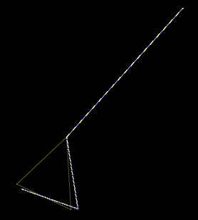
; Draws a figure
; Based on code by Christopher Tumber
; Based on work by [email protected]
; (c) 2007 [email protected]
; Public Domain for all Vectrex freaks

; First we rename all the BIOS routines
; we'll be needing

waitrecal       EQU   $f192
movepen7ftod    EQU   $f2fc
intensitytoA    EQU   $f2ab
movedrawVL4     EQU   $f3b7
draw_to_d       EQU   $f3df
ROTVL           equ   $f610

; *** Needed variables
rotangle        equ   $c886    ; Rotation angle
rotated         equ   $c890    ; Takes up some RAM
                               ; (the rotated coordinates)

; You can give them your own names if you want to
; just make sure you understand them, and preferably
; that someone else reading your source code
; understands them as well. (EQU = equals)
; All programs start from address $0000
; In this example, all numbers are actual numbers
; not hexadecimals like in the tutorials
; Assembly is quite capable of handling real numbers
: and they are much more easy for a beginner to
; understand
        ORG   $0000

; Init block that needs to be in every program
; the GCE text has to be in place, it is checked
; by BIOS
        FCB   $67,$20
        FCC   "GCE SIEG"
        FCB   $80
        FDB   music
        FDB   $f850
        FDB   $30b8
        FCC   "DRAWING"
        FCB   $80,$0

        clra                     ; Reseting rotation angle
        sta   rotangle

draw_line:
        inc   rotangle           ; Increase rotation angle

;Draws a line from the middle of screen to top right edge.
        jsr   waitrecal          ; Reset the CRT
        lda   #0                 ; Get y
        ldb   #0                 ; Get x
        jsr   movepen7ftod       ; go to (x,y)
        lda   #$7f               ; Get the Intensity
        jsr   intensitytoA       ; Set intensity
        lda   #127               ; Get y
        ldb   #127               ; Get x
        jsr   draw_to_d          ; draw a line to (x,y)

; draw some vectors
        ldx   #figure            ; Load the vector list
        ldb   #3                 ; Number of vectors
        lda   rotangle           ; Rotation angle
        ldu   #rotated           ; Save to pyoritetyt
        jsr   ROTVL              ; Rotates the coordinates

        jsr   waitrecal          ; Resets the BIOS
        lda   #127               ; Gets the Intensity
        jsr   intensitytoA       ; Sets the Intensity

        lda   #0                 ; Y - coordinate
        ldb   #0                 ; X - coordinate
        jsr   movepen7ftod       ; Moves pen to (Y,X)
        ldx   #rotated           ; Gets the rotated vector list
        lda   #3                 ; Number of vectors
                                 ; = how many vectors
                                 ; will be drawn, the
                                 ; starting point isn't
                                 ; counted
        ldb   #$80               ; gets the scale
        jsr   movedrawVL4        ; BIOS-routine that
                                 ; draws the vector
        bra   draw_line          ; jumps back to start

; It jumps back, because on Vectrex, you have to be
; drawing all the time to keep the vectors visible

; bra = branch
; lda = load to register a
; ldb = load to register b

; ein Dreieck
figure:
       fcb   0,0         ; 0,0 = Bildschirm-Mitte
       fcb   -64,32      ; y=-64=gehe 64 Pixels nach unten und x=32=gehe 32 Pixels nach rechts
       fcb   0,-64       ; y=0=bleibe an y-Position und x=-64=gehe 64 Pixels nach links
       fcb   64,32       ; y=64=gehe 64 Pixels nach oben und x=32gehe 32 Pixels nach rechts

music:
       FDB   $fee8
       FDB   $feb6
       FCB   $28,$08
       FCB   $0,$80


; This basicly tells Vectrex to play nothing
Space Ship
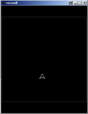
; ### Public Domain for all Vecfreaks
; ### Testing my abilities so far...
; ### Code & comments by [email protected]
; ### Needed BIOS routines

WAITRECAL      equ    $f192
INTENSITY      equ    $f2ab
PRINTSTR       equ    $f37a
RESET0REF      equ    $f354
MOVEPEN        equ    $f2fc
MOVEDRAW       equ    $f3b7

JOYDIGITAL     equ    $f1f8  ; Reads joystick positions
JOY1XENABLE    equ    $c81f  ; Enables joystick 1 X
JOY1YENABLE    equ    $c820  ; Enables joystick 1 Y
JOY2XENABLE    equ    $c821  ; Enables joystick 2 X
JOY2YENABLE    equ    $c822  ; Enables joystick 2 Y
JOY1X          equ    $c81b  ; Joystick 1 left/right
JOY1Y          equ    $c81c  ; Joystick 1 up/down
READBUTTONS    equ    $f1ba  ; Reads joystick buttons

alusx          equ    $c881  ; Space ship x position
alusy          equ    $c882  ; Space ship y position

; ### Here we go.

    org    0

; ### The required init block.

    fcb    $67,$20
    fcc    "GCE MANU"
    fcb    $80               ; All text ends with $80
    fdb    $fd0d             ; Play song "$fe38" from ROM
    fdb    $f850             ; Width, height
    fdb    $30b8             ; y-position, x-position
    fcc    "SPACE SHIP"
    fcb    $80,$0            ; Init block ends with $0

; ### Okay, this sets up the joystick checks, and only
; ### allows them for joystick 1, thus saving us a few
; ### hundred cycles. Don't forget to set joystick 2
; ### to 0, if you don't need it.

    lda    #1                ; 1 is the flag to enable
    sta    JOY1XENABLE       ; joystick 1 X
    lda    #3                ; 3 is the flag to enable
    sta    JOY1YENABLE       ; joystick 1 Y
    lda    #0
    sta    JOY2XENABLE       ; 5 would enable this
    sta    JOY2YENABLE       ; 7 would enable this
    lda    #-50              ; Set the starting y-coordinate
    sta    alusy             ; of the space ship to -50

; #################################
; ### Here's the actual program ###
; #################################

tikku
    jsr    WAITRECAL         ; BIOS recalibration

; ### The space ship

    jsr    RESET0REF         ; Beam to the center
    lda    #127
    jsr    INTENSITY         ; Sets intensity to 127
    lda    alusy             ; Y - coordinate
    ldb    alusx             ; X - coordinate
    jsr    MOVEPEN
    ldx    #alus             ; Drawing the space ship
    lda     #17              ; Number of vectors
    ldb    #128              ; Scaling
    jsr    MOVEDRAW

; ### Let's frame the area

    jsr    RESET0REF         ; Beam to the center
    lda    #30
    jsr    INTENSITY         ; Intesity to 30
    lda    #0                ; Y
    ldb    #0                ; X
    jsr    MOVEPEN
    ldx    #reunat           ; Drawing the edges
    lda    #8                ; Vectors
    ldb    #128              ; Scaling
    jsr    MOVEDRAW

; #########################
; ### Reads the buttons ###
; #########################

butt1
    jsr    READBUTTONS
    cmpa   #0                ; Compares a to 0
    lbeq   lovejoy           ; If it was 0 -> lovejoy
                             ; Otherwise
    bita   #$01              ; Tests for button 1
    lbeq   lovejoy           ; If it wasn't button 1
                             ; If it was button 1 ->

; ##########################
; ### Reads the joystick ###
; ##########################

lovejoy
    jsr    JOYDIGITAL        ; Reads joystick
    lda    JOY1X             ; Joy 1 X position to A
    lbeq   noxmove           ; If 0 -> jump to noxmove
    lbmi   lmove             ; If negative -> lmove

; ### If something else (positive)           ###
; ### the joystick has been moved right.     ###
; ### Limiting the maximum x-value to 118    ###

rmove
    lda    alusx             ; Value of alusx to A
    cmpa   #118              ; Compare A to 118
    lbeq   xiso              ; If it is 118 -> xiso
    inc    alusx             ; Increase alusx
    bra    xready            ; Jump to xready

xiso
    lda    #118              ; Load 118 to A
    sta    alusx             ; Store A to alusx
    bra    xready            ; Jump to xready

; ### Joystick has been moved left.          ###
; ### Limiting the minimum y-value to -118   ###

lmove
    lda    alusx             ; Value of alusx to A
    cmpa   #-118             ; Compare A to -118
    lbeq   xpieni            ; If it is -118 -> xpieni
    dec    alusx             ; Decrease alusx
    bra    xready            ; Jump to xready

xpieni
    lda    #-118             ; Load -118 to A
    sta    alusx             ; Store A to alusx
    bra    xready            ; Jump to xready

; ### Joystick hasn't been moved left or right.

noxmove

; ### Done with checking if the joystick
; ### was moved left or right, now checking
; ### if it was moved up or down.

xready
    lda    JOY1Y             ; Joy 1 Y position to A
    beq    noymove           ; If 0 -> jump to noymove
    bmi    dmove             ; If negative -> dmove

; ### If something else (positive)          ###
; ### the joystick has been moved up.       ###
; ### Limiting the maximum y-value to 126   ###

umove
    lda    alusy             ; Value of alusy to A
    cmpa   #126              ; Compare A to 126
    lbeq   yiso              ; If it is 126 -> yiso
    inc    alusy             ; Increase alusy
    bra    yready            ; Jump to yready

yiso
    lda    #126              ; Load 126 to A
    sta    alusy             ; Store A to alusy
    bra    yready            ; Jump to yready

; ### Joystick has been moved down.         ###
; ### Limiting the minimum y-value to -111  ###

dmove
    lda    alusy             ; Value of alusy to A
    cmpa   #-111             ; Compare A to -116
    lbeq   ypieni            ; If it is -116 -> ypieni
    dec    alusy             ; Decrease alusy
    bra    yready            ; Jump to yready

ypieni
    lda    #-111             ; Load -116 to A
    sta    alusy             ; Store A to alusy
    bra    yready            ; Jump to yready

; ### When making the limits (ie. how far)
; ### the ship can go, you have to count in
; ### the size of the ship. Best way to do this
; ### is to try it out. Ships 'hot spot' is
; ### where the first vector starts from.

; ### Joystick hasn't been moved up or down.

noymove

; ### Done with checking if the joystick has
; ### been moved up or down - so let's go
; ### back to the beginning and check all again.

yready
   lbra    tikku              ; Repeat

; ### You need LBRA, because BRA is too short a jump
; ### to jump to the beginning all the way from here

; ### Then all the coordinates that are needed

alus
    fcb     0,0               ; Tip of the ship
                              ; also the 'hot spot'
    fcb    -3,2
    fcb    -3,1
    fcb    -2,0
    fcb    -3,1
    fcb    0,2
    fcb    -3,2
    fcb    0,-3
    fcb    2,-2
    fcb    0,-6
    fcb    -2,-2
    fcb    0,-3
    fcb    3,2
    fcb    0,2
    fcb    3,1
    fcb    2,0
    fcb    3,1
    fcb    3,2

reunat
    fcb    126,-126
    fcb    0,126
    fcb    0,126
    fcb    -126,0
    fcb    -126,0
    fcb    0,-126
    fcb    0,-126
    fcb    126,0
    fcb    126,0
Pong Game
Einfaches aber vollst�ndig funktionierendes Pong Spiel.
; it is public domain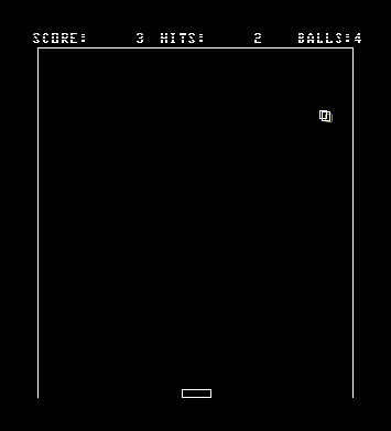
Ski Game
Einfaches Skiabfahrt 'Spiel'. Kein komplett fertiges Spiel, aber ein funktionierendes Grundger�st.
; v0.03a
; This source code is copyright Andrew Coleman
; This whole thing is Freeware.
; You can play around with it, steal bits of it, do whatever you want with it really,
; but please DO NOT distribute any modified versions of this source without my permission.
; Big thanks go out to Chris Salamon, without his programming docs i'd never have gotten
; this far.