Robotics is one of the subjects that captivates every true electronics engineer's heart. However, the work on most of these robots seems to saturate with a wired and the user friendly (albeit some interference!) wireless version. As a part of our Electronics Workshop, we decided to take that extra step and make our wireless robot controlled centrally by a terminal.
The aim of this project has been to come up with a basic working model of a wireless robot that can be controlled by a remote computer. This concept makes use of sending signals to the transmitter through the Parallel Port. The project has extensive use in diverse fields ranging from Fault Detectors in large scale industries or even space exploration, provided there is a significant increase in the range.
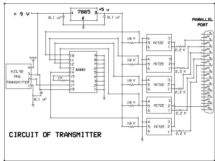
TRANSMITTER
The transmitter circuit of the robot is responsible for sending the user initiated signals on PC to the robot. The transmitter is connected to the PC's parallel port using the RS232 connector. The user selectively sets or resets individual bits of the Parallel Port and these signals are isolated using opto-couplers (MCT2E). It is then fed to the encoder (A5882) for encoding. The signals are then modulated at a unique frequency decided by the combination of switches. The modulated signal is then transmitted to the robot by the antenna.
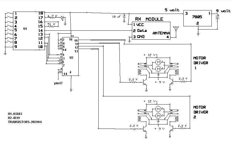
RECIEVER
The Receiver end of the circuit, installed on the chassis is tuned to receive the encoded signal at the frequency set by the user at the transmitter end. The Decoder (A5883) decodes the signal which is then fed to the multiplexer. Depending on the type of signal received, the multiplexer drives the appropriate motors. The motor driving circuit consists of Relays, transistors and resistors.
Each of the two sides of the chassis has two motors connected to the relay. Relays 1 and 2 will affect the direction of rotation of motors of one side while the other two relays affect the other side. Hence, turning can be achieved by activating either relays 1 and 3 or relays 2 and 4.
OPERATING PROCEDURE
1. Connect the transmitter circuit to the parallel port of PC. Power on the
transmitter circuit
2. Power on the receiver circuit and connect the battery in place.
3. Open the software "Paramon"
4. Each of the dots indicates the individual pin of the Parallel port. By Default,
a red indicates "high" signal while a "green" indicates
a low signal.
5. Each of the bit D4-D7 represents a signal. Clicking on each of the dots sets/resets
the corresponding bit and hence drives the motor in the corresponding direction.
6. The port no indicates the port at which the robot is interfaced. The function
of each of the bits may vary with PC.
7. To change the direction of motor movement, initiate a new signal by clicking
on the corresponding bit.
SPECIFICATIONS:
" Range : 1-5 m
" Battery Current Rating:
" Supply to Transmitter: +9V
" Supply to Receiver: +9V
Project By:
" Srinath G Iyer
" Akshay Kakar
" Pratik Maheshwari
HOME