| Helm The helm officer is responsible for plotting the safest, most efficient course of travel and for coordinating with OPS and TAC to take into account their considerations for plotting approaches to systems, etc. Moreover, helm handles stellar cartography and keeps star charts updated. |
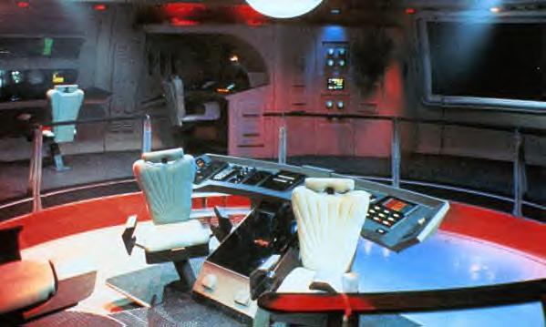
| Helm has specific duties and responsibilities. In a word, the Helm is the Pilot. The Helm takes orders and directions from the Commanding Officer. If the Commanding Officer is not available then the Helm takes commands directly from the Executive Officer.� The five major areas of responsibility for the Helm or Flight Control Officer or Conn. �� � Navigation references and course plotting �� � Supervision of automatic flight operations �� � Manual flight operation �� � Position verification �� � Bridge liaison to engineering department for flight and warp control There are three different options when selecting powered spaceflight. �� � Thrusters �� � Impulse �� � Warp The Flight Control Panel has 7 major components for a ship and 9 components, two additional components for a space station. �� � Emergency Override Selection �� � Thruster System Control �� � Impulse System Control �� � Warp Drive Systems Control �� � Navigational Reference Display �� � Manual Sequence Controls �� � X-Y Transition Pad Control �� � Attitude and Translational Control �� � Pylon and Gondola Controls The Helm control access is initiated by palm scan and security code voice command in order for the Helm to respond.� Helm security is initiated when an appendage is placed on the console. Power comes on the console when security has cleared.� Controls are adaptable for the species assuming command of the helm. Responsibility of Helm Navigation references and course plotting This component displays reading for navigation and tactical sensors, overlaying them with both the current positional and course projections along with options available to the Helm. In the event that a maneuver exceeds the capacity of the ship the Inertial Damping System (IDS) will request the Helm to modify the flight path. During Alert status, flight plan program allows Helm to override the Safety Auto Lockout for the IDS. Supervision of automatic flight operations Monitoring of automatic flight controls are simply visual oversight and periodic systems checks of the automatic flight controls. These are usually performed during routine flights.� The Automatic flight controls must be select off unless the ship engages the Alert status of Yellow or higher levels. Manual flight operation There are several different modes of manual flight once auto flight has been deselected.� They are manual navigation, manual navigation projections, and Helm control. Manual navigation is nothing more then plotting the course free of the nav system.� A kind of off road way to travel. It is use primarily to maneuver around in Nebula's and Ion or Tachyeon fields.� Additionally, the manual flight option is used for separating the saucer from the battle ship and reconnecting the two sections when ready. Position verification The Helm is responsible for setting and maintaining the flight course of the ship.� Before a ship can go toward a place the Helm must know where in space the ship is current located.� It is called the Ship's Relative Position. Space is height, width, length and depth much like flying in the sky of a planet.� Charting and course plotting is described in those four dimensions by describing Heading, Bearing, Mark and Azimuth in measurements of degrees. The heading is the direction of flight. It is defined in terms of 000.� Bearings are measurements of relative height to the ship altitude. The Mark is the relative position of the ship in relationship to the galaxy center. Azimuth is the angle by degree away or toward that center.� Like the radius of a circle there are 360 degrees to the Azimuth. The Azimuth is the angle out from the ships present position. So turning 30 degrees port is turning 30 degrees to the right without changing elevation. All positions are based on the current orientation of the spacecraft to the center of the galaxy. So to change ships position the heading, bearing, mark and Azimuth must be changed.� Bridge liaison to engineering department for flight and warp control Helm coordinates the throttle control on the console. There are three different� flight power systems on a ship and there are three different controls on the power component of the console. The three power sources are thrusters, impulse and warp.� The current power source must be disengaged before another power source can be engaged.� When there is a malfunction of the power systems either Engineering directly or Operations can make adjustments to the power sources in order to reroute power to throttle controls.� It is the responsibility of Helm to repair damage to the Helm console. Powered spaceflight. Thrusters are used for the intricate docking and backing out maneuvers so important when moving in heavy traffic while attempting to connect with a host star base gondola.� Thrusters are also used to make slight course change adjustments. Impulse is the principal sublight propulsion on the ship and for certain auxiliary power units like Emergency Pod and Warp Core Ejection.� Impulse is measured in �, �, � and full impulse. There may be two power fusion engines on a star ship, one for main impulse and the second for the saucer module. Both can be managed by Helm at the same time on the main bridge as long as the Saucer is still locked into the battle section. Warp is the power source for speed beyond light speed. It is measure in cochrans. Warp factors are figured from Warp 1 which is the lowest warp to warp 9.� Warp speed is dependent upon interstellar conditions like gas density, electric and magnetic fields and fluctuations in the sub space domain as well as energy penalties resulting from quantum drag forces and power oscillation inefficiencies. There are different Warp limits based on the application of the ship. When towing another ship the warp limit is no higher than Warp 5 for a safe and controlled flight. Warp is not possible when separating or relinking between the saucer and battle section. The Flight Controls are the component sections on the console. Emergency Override Selection is the Pad switch by the helm control at the 1 o'clock position.� Thruster System Control is the first control to the left in the power system group. Thruster control can be used in conjunction with both the impulse and the warp drive system, or it can be used as an independent system. Impulse System Control is part of the power system group of three switches in the Thruster, Impulse, and Warp cluster.� Impulse control is the middle switch.� � � � � � � � � � � � � � � � � �� Warp Drive Systems Control is also a part of the power system cluster.�� Warp is the switch on the right. Navigational Reference Display is the on-console on-screen display which can select out the Tactical weapons grid and the Projected flight path analysis overlays. Manual Sequence Controls are a lock out switch for the automatic helm and navigation system on the Helm Console. When the� manual sequence controls are selected all the Helm controls are operated by the Helmsman.� The helmsman can place any or all of the three systems back on computer by selecting manual override release. X-Y Transition Pad Control is a way to input galactic coordinates directly from the nav computer, another source or thru the OPS and/or Tac console to locate or project flight path or combat maneuverability coordinates and place that data on the screen. Attitude and Translational Control is the primary system to keep a space station in a stable synchronous orbit and in planar stabilization by the Reaction Control System.� It can be selected off thru a series of command and security clearance codes which will allow the space station to be either computer or manually repositioned. Pylon and Gondola Controls are the primary receiver for docking ships. The Pylon and Gondola controls not only moves the docking ramp system but also tractors the ship securely against the docking port exterior clamps and transfer tunnels. It can be manually or computer manipulated.�� A few words about external sensors. They are the senses for the Helmsman which permit the navigation of a very large star ship in very tight spaces like docking rings and around graviton, and stellar anomalies. They are made up of six components, graviton detectors, stellar pair coordinate imagers, pulsar/quasar counters, far infrared scanners, and Federation Timebase Beacon receivers. They feed data about the structural integrity field and inertial damping field processor, inertial sensors to the Helm. Manual Written by: Fleet Captain Jaccob Adder Ref: Star Trek the Next Generation Technical Manual and � � � �� Star Trek Deep Space Nine Technical Manual |
 |
| HELM |

|
|
|
|
|