Written by Sean Monk
(www.seans-eclipse.tk)
Wiring Diagram for 1990-1994 DSM's
Always check the polarity of wires before tapping into them, as the following table may be incorrect for some wires.
| Vehicle Wire | Wire Color | Wire Location or Note |
|---|---|---|
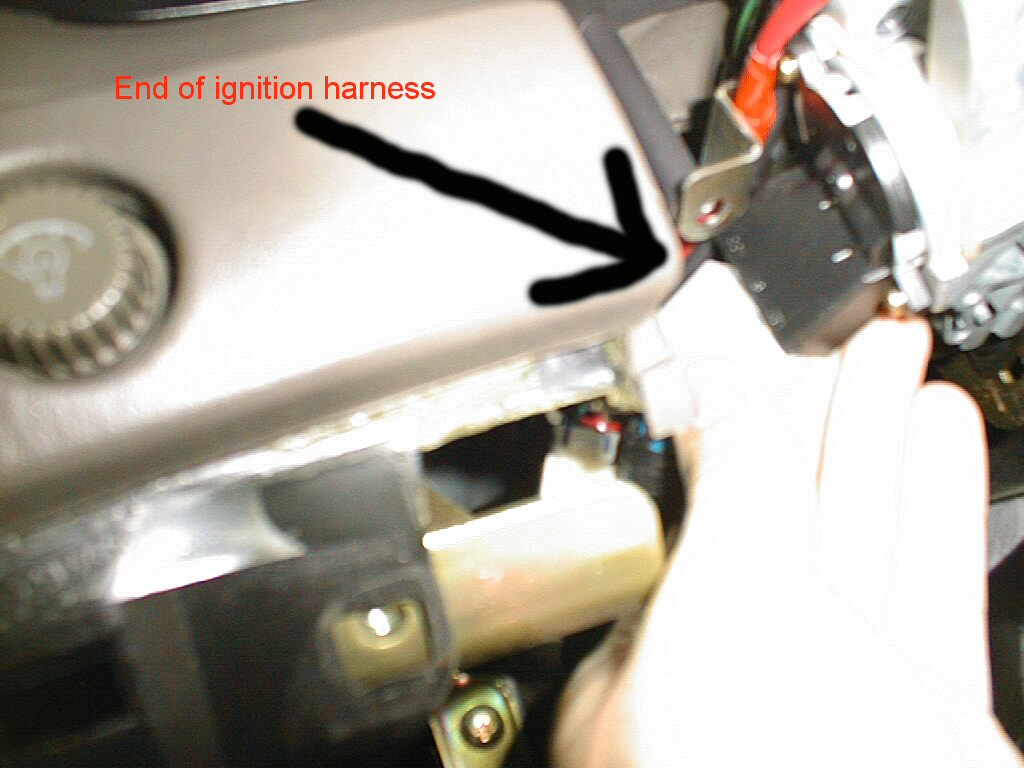
| Constant 12 Volts | White | Ignition Switch Harness |
| Ignition 12 Volts | Black/White | Ignition Switch Harness |
| Starter | Black/Yellow | Ignition Switch Harness |
| Parking Lamp | Green/White | (+) at relay |
| Dome Light | Green/Red | (-) Driv pin switch or dome light |
| Trunk pin switch | Black | (-) Luggage compartment light or switch |
| Trunk release | N/A | (must add actuator) |
| Radiator Fan | Blue/White | (+) Radiator fan |
| Power antenna | White/Black | (+) Radio |
| OEM Alarm Arm | N/A | |
| OEM Alarm Disarm | Brn/White, Brn/Blk | (-) Either kick panel Tie to ground to permanently disable the alarm |
| OEM horn | Green/Black | (-) Steering column harness, only on relay |
| Headlights | Red/Blue | (-) Underhood relay or headlights |
| Ign Key Warning | Yellow/Green | (+) Steering column harness |
| Door Lock | Brown/White | **at relays on relay block to left of steering column (these are negative trigger wires)** |
| Door Unlock | Brown/Blue | |
| Window Driver UP | Red | At driver's switch (these need relays to apply 12V to the respective wire to move the window up or down) |
| Window Driver DOWN | Green | |
| Window Pass UP | Red/Blue | |
| Window Pass DOWN | Black/Blue | |
| Ignition #2 | Blue/Black | Ignition Switch Harness (heater/AC) |
| Accessory | Blue | Ignition Switch Harness (wiper/radio) |
| Tach signal | White | At tach filter or power transistor (see note 170) |
| Reverse Light | Red/Blue | (+) at switch on top of transaxle |
| Neutral Safety | NOT GRND TYPE | OEM switch opens starter circuit |
| Brake Light | Green | (+) switch on brake pedal bracket |
| Driver front speaker | White/Blue (+) Black/Blue (-) |
|
| Pass front speaker | White/Red (+) Black/Red (-) |
|
| Driver Rear speaker | Yellow/Blue (+) Gray/Blue (-) |
|
| Pass Rear speaker | Yellow/Red (+) Gray/Red (-) |
|
Notes:

    170  1.8 liter - tach filter on front center of engine, has 3 pin plug,
         white is filtered signal to tach, white/black is signal from coil.

         91-93 2.0 liter and 2.0 turbo - power transistor on passenger rear
         of engine below coil, on 8 pin plug, white wire at pin #4.
         1990 2.0 liters used filter same as 1.8 liter.
| ||
Wiring Diagram for 1995+ DSMs
Always check the polarity of wires before tapping into them, as the following table may be incorrect for some wires.
| Vehicle Wire | Wire Color | Wire Location or Note |
|---|---|---|
| Constant 12 Volts | White | Ignition Switch Harness |
| Ignition 12 Volts | Black/White | Ignition Switch Harness |
| Starter | Black/Red | Ignition Switch Harness |
| Parking Lamp | Green/White | (+) at relay or fuse block (#5) |
| Dome Light | Red/Green | (-) Driv pin switch or dome light |
| Trunk pin switch | Red/White | (-) Luggage compartment light or switch |
| Trunk release | N/A | (must add actuator) |
| Radiator Fan | White/Black and White/Blue |
(+) Radiator fan |
| Power antenna | ?? | (+) Radio |
| OEM Alarm Arm | Green/Yellow | (-) Driver's kick panel |
| OEM Alarm Disarm | Green/White, Brn/White, Brn/Blk | (-) Either kick panel Tie to ground to permanently disable the alarm |
| OEM horn | Green/Black, Green/Red | (-) Steering column harness |
| Headlights | Red | (-) Headlight switch |
| Ign Key Warning | Green/Yellow | (-) (with key out) Steering column harness |
| Door Lock | Brown/White | **at relays on relay block to
left of steering column - 3 wire neg
(these are negative trigger wires)** Unlock driver door only - Blue/Red in driv kick panel |
| Door Unlock | Brown | |
| Window Driver UP | Green/Red | Main switch (these need relays to apply 12V to the respective wire to move the window up or down) |
| Window Driver DOWN | Green/Blue | |
| Window Pass UP | Brown/Yel | |
| Window Pass DOWN | Green/Yell | |
| Ignition #2 | Blue/Black | Ignition Switch Harness (heater/AC) |
| Accessory | Blue | Ignition Switch Harness (wiper/radio) |
| Tach signal | White | Pin 6 at 18pin connector behind driver's side of console Note #446 |
| Reverse Light | Red/Blue | (+) at switch on brake pedal bracket |
| Neutral Safety | Brown/Red | At switch on transaxle |
| Brake Light | Green | (+) switch on brake pedal bracket |
| Driver front speaker | White/Blue (+) Black/Blue (-) |
Color for dash speakers - driv and pass and door speakers are: (+) Black/White, (-) Black |
| Pass front speaker | White/Red (+) Black/Red (-) |
|
| Driver Rear speaker | Yellow/Blue (+) Gray/Blue (-) |
|
| Pass Rear speaker | Yellow/Red (+) Gray/Red (-) |
|
|
Notes: 446 Can also be found at tach filter on power transistor. Turbo has tach test connector on passenger firewall. Also at Pin #8 on ECU in non-turbo engine control module on driver wheelwell. |
||
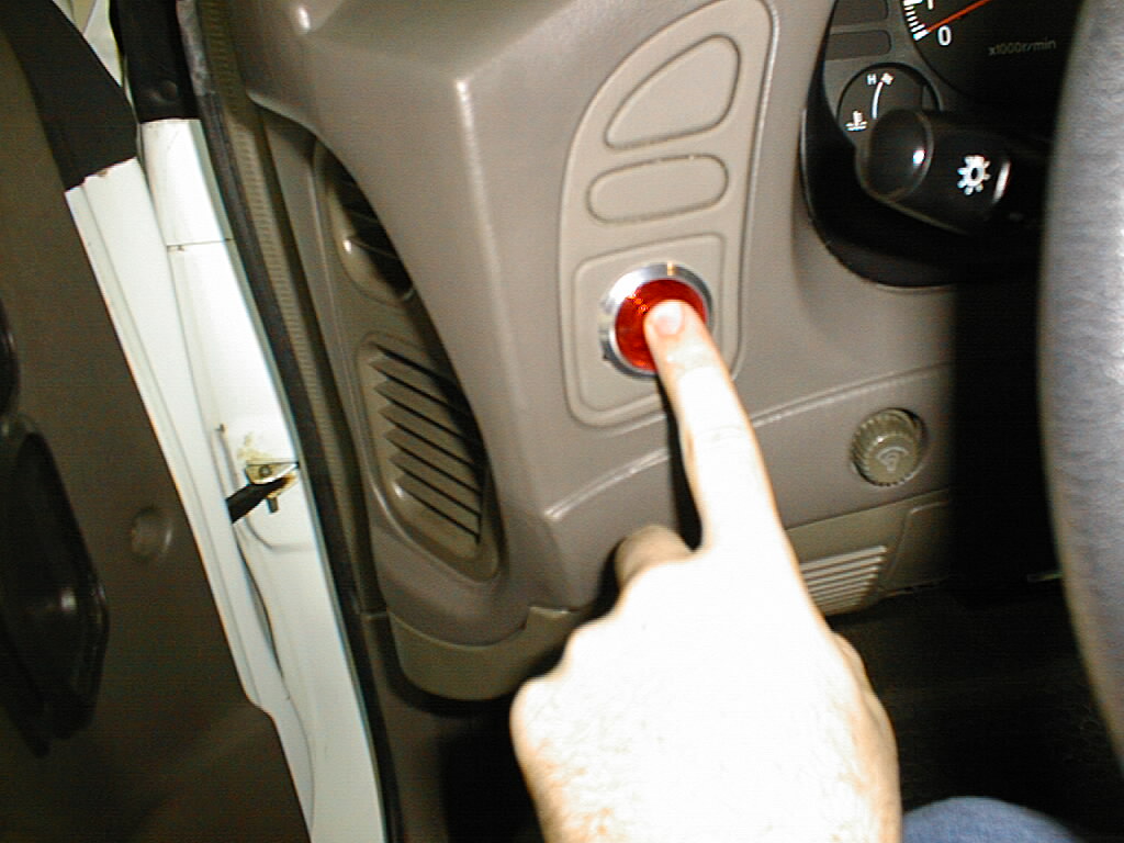
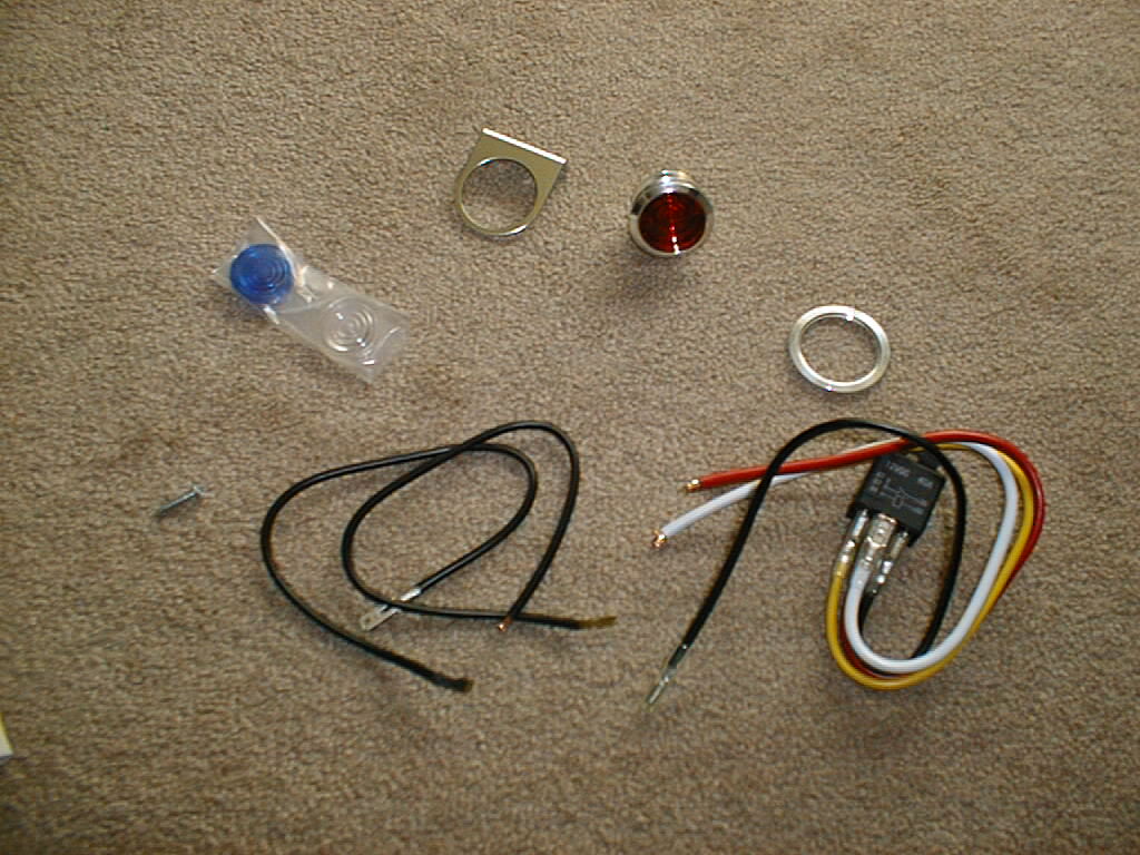
Ok, now you have bought your push button start right? Should look something this below...
-----------------------------------------
The wiring of the push button starter i purchases is as follows, please adjust accordingly-
*Red Wire to be connected to 12v constant
*Yellow Wire to be connected to ignition wire
*White wire to be connected to starter wire
*Black wire to be connected to switch, and then the other wire from the switch is to be connected to the ground.
Next, tap into the Ignition 12 volt (black/white) wire from your car. After you have exposed the wire, connect the yellow wire to the ignition 12 volt (black/white) and secure this wire in place.
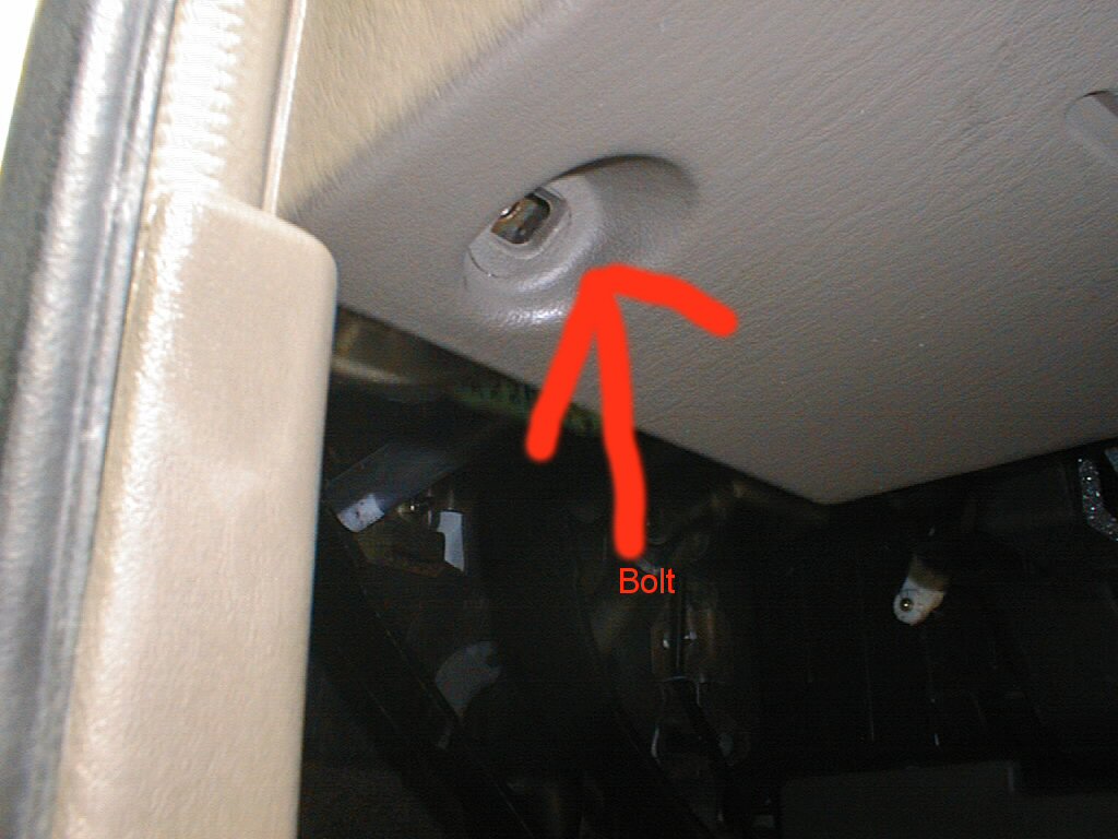
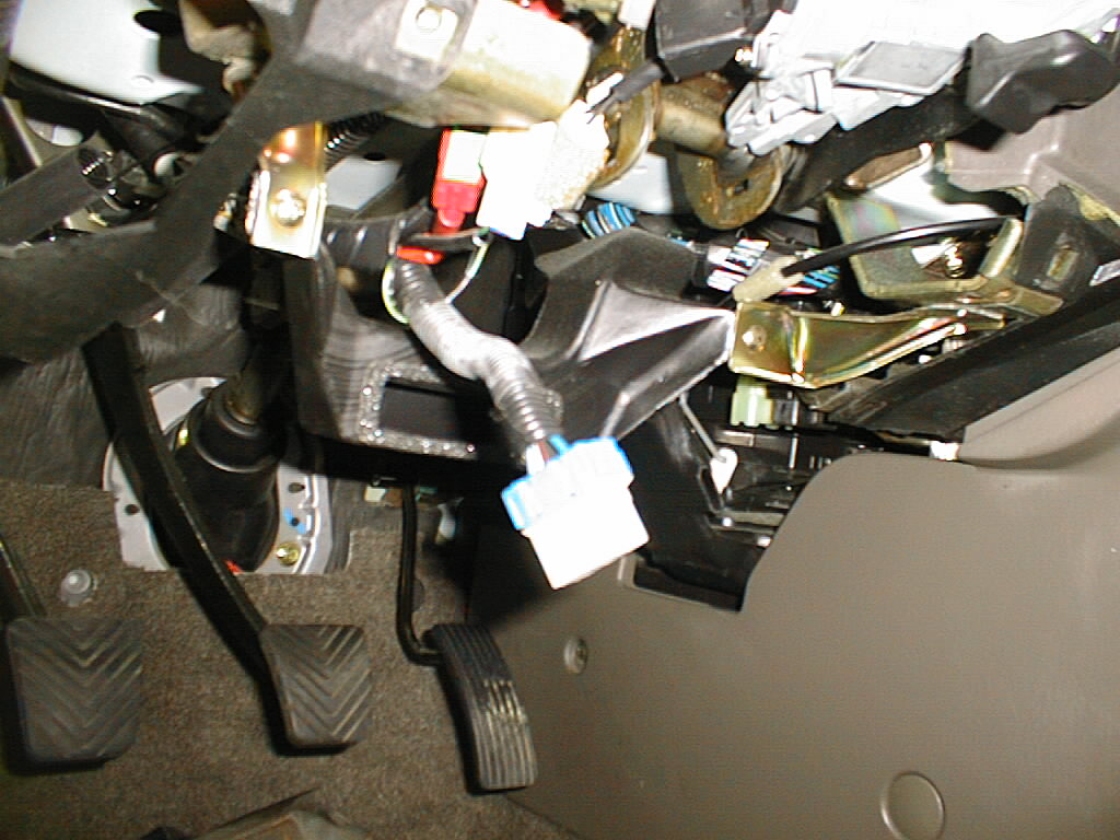
Next, Tap into the starter wire from the vehical (Black/Red). You may cut this wire complete off from the vehicle if you do not want to be able to start the vehicle with the key anymore, but only with the button. After you have either exposed the Starter wire from the vehicle (Black/red), or cut the wire, connect the wire comming from the vehicle to the white wire. After you have done this, conect the black wire comming from the relay box of the push button starter to the button itself. Connect the wire from the other pin of the button to a good ground location (bolt that makes contact with the chassy of the car). Before you install the button into the vehicles interior, you should make sure you have wired this correct, so insert the key and turn it all the way to the on position, next is press the button (holding the clutch for m/t drivers) and the vehicle should power on, only hold down the button until the vehicle has successfully started, and then release the button.