This robot also incorporates a touch sensor underneath that detects when the speedometer assembly pivots down too far, thus indicating that the robot is approaching a dropoff (at which point it's a good idea to stop the robot).
This is a design we came up with to use with a robot that wanders around the room. We kept having problems with using touch sensors and bumpers to detect obstacles -- things like deep carpet would not affect a bumper, but could still stop the robot. So we needed a way to measure the speed of the robot -- that way, you can simply check for when the speed is 0 (or some small number) and therefore know that your robot has run into some sort of obstacle. Our solution uses a touch sensor to measure the revolutions of an axle with wheels on it that is attached to the robot. It's best explained with pictures as shown below...
These drawing were produced using LeoCAD - a great program!
| |
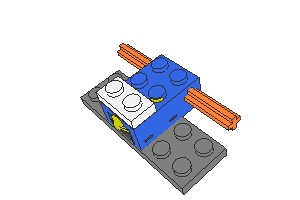
Step 1 for making the speedometer. The white brick is a 1X2 electric element -- the wire to the RCX is connected to it. |
| |
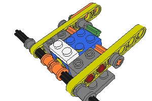
Step 2. |
| |
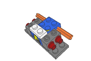
Step 3. The two axle bushings which contact the touch sensor must be positioned carefully. When lined up right, the touch sensor will get activated 4 times for each revolution of the axle. |
| |
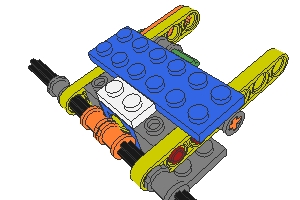
Step 4. The blue 2X6 plate helps hold the whole thing together. |
| |
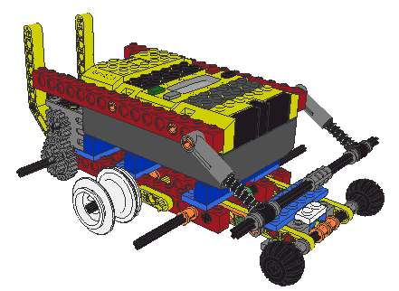
This is a robot that uses the speedometer. It is propelled with caterpillar
tracks (not shown). The two small wheels in front are the
"speedometer" wheels which are used to determine when the robot has
encountered an obstacle. The spring-loaded "bumper" in the front it
to keep the speedometer assembly from pivoting up too far and hitting the RCX.
This robot also incorporates a touch sensor underneath that detects when the speedometer assembly pivots down too far, thus indicating that the robot is approaching a dropoff (at which point it's a good idea to stop the robot). |