 |
|
|
|
|
|
|
|
|
|
|
|
|
|
|
|
|
|
|
|
|
|
|
|
|
|
|
|
|
|
|
|
|
|
|
|
|
|
|
|
|
|
|
|
|
|
|
 |
|
|
|
 |
|
|
|
 |
|
|
|
|
|
|
|
|
|
The Right Elevator |
|
|
|
|
 |
|
|
|
|
|
|
The elevators are similar in construction to the rudder, with only the external dimension being the significantly different. I began with the right elevator as it is the easier of the two. The left elevator incorporates a trim tab which makes it a little trickier.
|
|
|
|
|
|
|
 |
|
|
|
|
|
|
|
|
|
|
|
|
|
|
|
|
|
 |
|
|
|
|
|
|
|
|
|
|
|
The counterweight holder is similar to that on the rudder. A C-frame is being used above to rivet the two halves together. |
|
|
|
|
|
|
|
|
|
 |
|
|
|
|
|
|
|
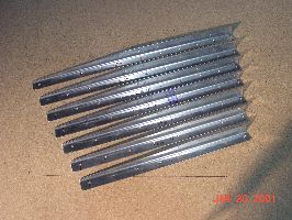
The first step was to fashion stiffeners out of angle aluminum. The stiffeners are riveted to the skin to keep it from deforming under air loads. |
|
|
|
|
|
|
|
|
|
 |
|
|
|
|
|
|
|
|
|
|
|
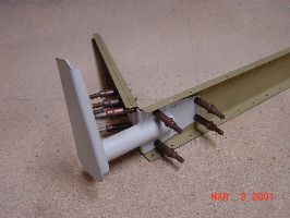
The counterweight holder is completed by riveting a heavy skin around the outside and attaching it to the end of the spar. Counterweigthts, shown here, are bolted to the inside. |
|
|
|
|
|
|
|
|
|
|
Once the desired rivet spacing is determined, it is transfered to the stiffeners and the holes drilled. The stiffeners are then used as templates to drill the skin. Once drilled and primed, the stiffeners are riveted to the skin (as shown above with the spar in position for initial fitting). |
|
|
 |
|
|
|
|
|
|
|
 |
|
|
|
|
|
|
|
|
|
|
|
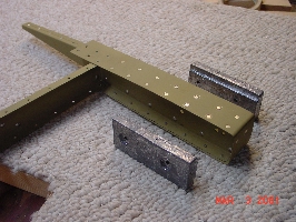
A welded steel control horn is riveted to the inboard end of the spar and will ultimately attach to both the end of the elevator pushrod and the center bearing of the horizontal stabilizer. The horn appears gray because it has been powder coated for corrosion protection. |
|
|
|
|
|
|
|
|
|
|
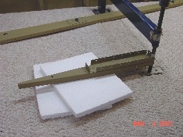
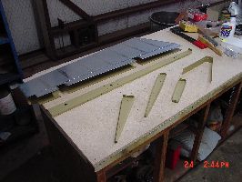
The spar and remaining skeleton parts are trial fitted and primed before being riveted together (as shown above). A wooden brake is then used to bend the trailing edge of the skin to its final shape. This is a critical step as a poor bend can adversely affect flying qualities, or destroy the parts all together. |
|
|
 |
|
|
|
|
|
|
|
 |
|
|
|
|
|
|
|
|
|
|
|
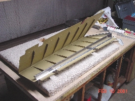
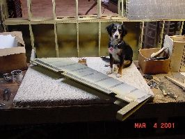
As with the rudder, the elevator is placed in a jig consisting of two upright blocks with notches cut in them. This ensures the elevator is free of warpage. The assembly is then riveted together. The finished product is shown above with only the bending of the leading edge remaining, which will be done at the same time as the left elevator. On to the left elevator! |
|
|
|
|
|
|
|
|
|
|
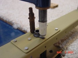
Reinforcements are riveted to the spar along with nutplates to receive rod end bearings that will act as hinges for the elevator. The cleko holds the nutplate in place while the other rivet is driven. |
|
|
|
|
|
|
back to main page |
|
|
|
|
|
|
|
|
|
|
|
|
|
|
|
|
|
|
|
|
|
|