Can Achieve Temperature, Pressure and Flow Control. Applicable to Chemical Industry, Industrial Process, Glass, Ceramics, Timbering, Papermaking, Food and Drinks Industry, Coal Fusion Industry, etc.
LG Programmable Logic Controller
·
8 PID Control
with Auto Tuning ( Built-in )![]()
Can Achieve
Temperature, Pressure and Flow Control. Applicable to Chemical Industry,
Industrial Process, Glass, Ceramics, Timbering, Papermaking, Food and Drinks
Industry, Coal Fusion Industry, etc.
·
A
High-Speed Arithmetic Counter
(
Built-in
)
A 16kHz Error Correcting
Arithmetic High-Speed Counter, Receive Signals From Coder and Pulse Generator.
Since the Operational Method of the High-Speed Processor Using Fractionalized
Self-Diagnosis Error Codes of CPU Module, so the Execution Counter is not
affected by the Scan Time. (1 Phase 16kHz, 2 Phase 8kHz, 24bit)
·
Pulse
Train Output (
Built-in
,
Transistor Type)
A High Frequency Pulse Output
(max.2kpps), Can Apply to Step-Up Motor and Simple Location
Control System.
·
8 Way
Pulse Catch Input (
Built-in
)
Pulse Catch Input can Detect the Pulse Input that
cannot be Detected by Normal Input Point, 8 Way of this kind of Input Method
(p000 ~ p007)
can be Set. Minimum Pulse Can be Detected is 0.2 ms, These Input Point can be
Defined by the Parameter Setting of KGLWIN.
·
Pulse
Filtered Input (
Built-in
)
Pulse Filtered Input Port can Prevent the CPU Receive
Abnormal Input, Reduce the Number of Errors. Pulse Filtering Time is
Programmable from 0 to 15 ms, Step up by 1 ms.
| Programmable Logic Controller (CPU Module) | ||||
| Digital Input Module Specification | Model | |||
K7M-DR20S  |
K7M-DR30S  |
K7M-DR60S  |
||
| Number of Input Points | 12 | 18 | 36 | |
| Insulation Device | Photo-Coupler | |||
| Rated Input Voltage | DC 24V | |||
| Rated Input Current | 7mA (I00 ~ I02: 15mA) | |||
| Operation Voltage Range | DC 20.4 ~ 28.8V (Ripple: Less than 5%) | |||
| Maximum Simultaneous On | 100% Simultaneously ON | |||
| On Voltage / On Current | DC 15V or Higher / 4.3mA or Higher | |||
| Off Voltage / Off Current | DC 5V or Lower / 1.5mA or Lower | |||
| Input Impedance | Approximately 3.3K (I00 ~ I02: 1.5K) | |||
| Response Time | Off→On | 1 ~ 15ms | ||
| On→Off | 1 ~ 15ms | |||
| I/O Indicator | LED Display | |||
| External Wiring | Terminal Block ( M3 x 6 Screws) | |||
| Digital Output Module Specification | Model | |||
| K7M-DR20S | K7M-DR30S | K7M-DR60S | ||
| Number of Output Points | 8 | 12 | 24 | |
| Switching Device | Relay (Transistor) | |||
| Insulation Device | Relay (Transistor) | |||
| Rated Load Voltage/Current |
DC 24V/2A (Load
Resistance),
AC 220V/2A (COSØ
= 1) / 1Point 24 / 1 Point/Common , 4A / 2 Point/Common , 4A / 4 Point/Common |
|||
| Minimum Input | DC 5V / 1mA | |||
| Maximum Load Voltage | AC 250VAC / DC 110V | |||
| Maximum Switching Frequency | 1200 Times per Hour | |||
| Surge Killer | None (Clamp Diode) | |||
| Service Life | Mechanical | 20 Millions Times or More | ||
| Electrical | 100,000 Times or More | |||
| Response Time | Off→On | 10ms or Less (Less Than 2ms) | ||
| On→Off | 12ms or Less (Less Than 2ms) | |||
| Operation Indicator | LED | |||
| External Connections | Terminal Block Connector (M3 x 6 Screws) | |||
|
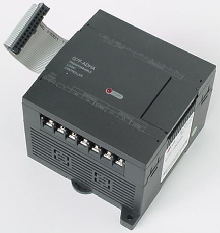
Digital / Analog Conversion Module I/O (G7F-ADHA) |
|||
| Item | Description | ||
| A/D Module | Conversion Input | Voltage | DC 0 ~ 10V |
| Current | DC 0 ~ 20mA (4 ~ 20mA when using FB ) | ||
| Digital Output | 12-bit ( 0 ~ 4000 ) | ||
| Voltage / Current Selection |
·
Select with the Input Conversion Switch on the Side of
the Module |
||
| Conversion Input Channel | 2 Channels / 1 Module | ||
| Output Offset | Voltage | DC -0.5V, +12V | |
| Current | DC -2mA, +25mA | ||
| D/A Module | Digital Input | 12-bit ( 0 ~ 4000 ) | |
| Conversion Output | Voltage | DC 0 ~ 20mA (External Load Resistance: 2K ~ 1M) | |
| Current | DC 0 ~ 20mA (External Load Resistance: 560 or Lower ) | ||
| Voltage / Current Selection | Select in accordance with the Input Terminals | ||
| Conversion Output Channel | 1 Channel / 1 Module | ||
| Maximum Output | Voltage | DC + 15V | |
| Current | DC + 24mA | ||
| Output Offset | DC 0 ~ 10V | 2.5mV (1/4000) | |
| DC 0~20 mA | 5 μA (1/4000) | ||
| Overall Accuracy | Less than ± 0.5% (Accuracy to full scale) | ||
| Conversion Time | Scan Time +1.5 ms / Channel | ||
| Isolation Method | Photo-Coupler Isolation between Input Terminals and Power Supply | ||
| External Connections | 14 Terminals | ||
| Power Supply | DC 24V, 80mA | ||
| Power Consumption | DC 5V, 10mA | ||
| Weight | 235kg | ||