FHSS
Frequency Hopping Spread Spectrum
- Modulation technique where signal is repeatedly switching frequencies during radio communication, minimizing probability of jamming/detection
- First used during Cuba Crisis
- Implemented In 802.11b (WiFi)
- Receiver hops between frequencies in synchronization with transmitter based on pseudo-random frequency sequence (explained later)
- Eavesdroppers hear only noise when in wrong frequency gap
- Attempts to jam signal on a frequency block succeed only at knocking out a few bits
- Used extensively when in hostile territory
- If message is lost due to interference, transmitter must resend data
- Can use Adaptive Frequency Hopping (Smart Hopping) to avoid this situation
- Preview channel before sending out signal
- If noise encountered, put channel at end of queue, if not, transmit as normal
FHSS Block Diagram
Figure 1
Frequency Hopping (Graphical Context)
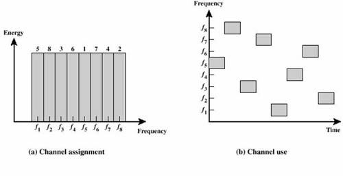
Figure 2
FHSS Performance Considerations
- Large Number of Frequencies Used
- Uses the ISM Band (Industrial, Scientific, and Medical) from 2.402 GHz � 2.479 GHz
- Has possible 79 hopping channels
- Each channel 1MHz wide (Hence the term Narrowband)
- 79 possible hopping channels divided into 3 groups
- Each hopping group consists of 26 blocks
(ex. 0,3,6,1,12,4�)
- Hops must take at most 224m
sec with dwell time at .4 seconds
- FCC requires at most 1 Watt output power
- Signal must be 99% confined to the channel being used
- Both values are low because must hop every 4mSec
Characteristics of Modulation
- GFSK most commonly used to encode bits (Gaussian Frequency Shift Keying)
- Encodes data as a series of frequency changes in a carrier
- Noise usually changes amplitude of signal, thus GFSK modulation tends to be relatively immune to noise
- Centered at center frequency, Fc
- Has 2-level and 4-level GFSK (similar to PAM)
- 4-Level encodes 2x more data during the same symbol rate
- Symbol Rate-rate you can send the next bit
- 4-Level is favored, but equipment more expensive
GFSK Wave Signals
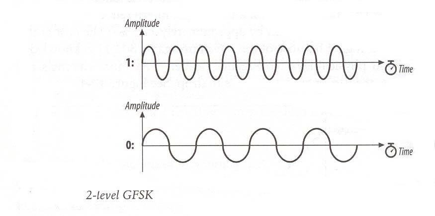
Figure 3
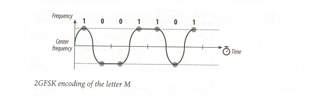
Figure 4
GFSK Wave Signals
(Continued)
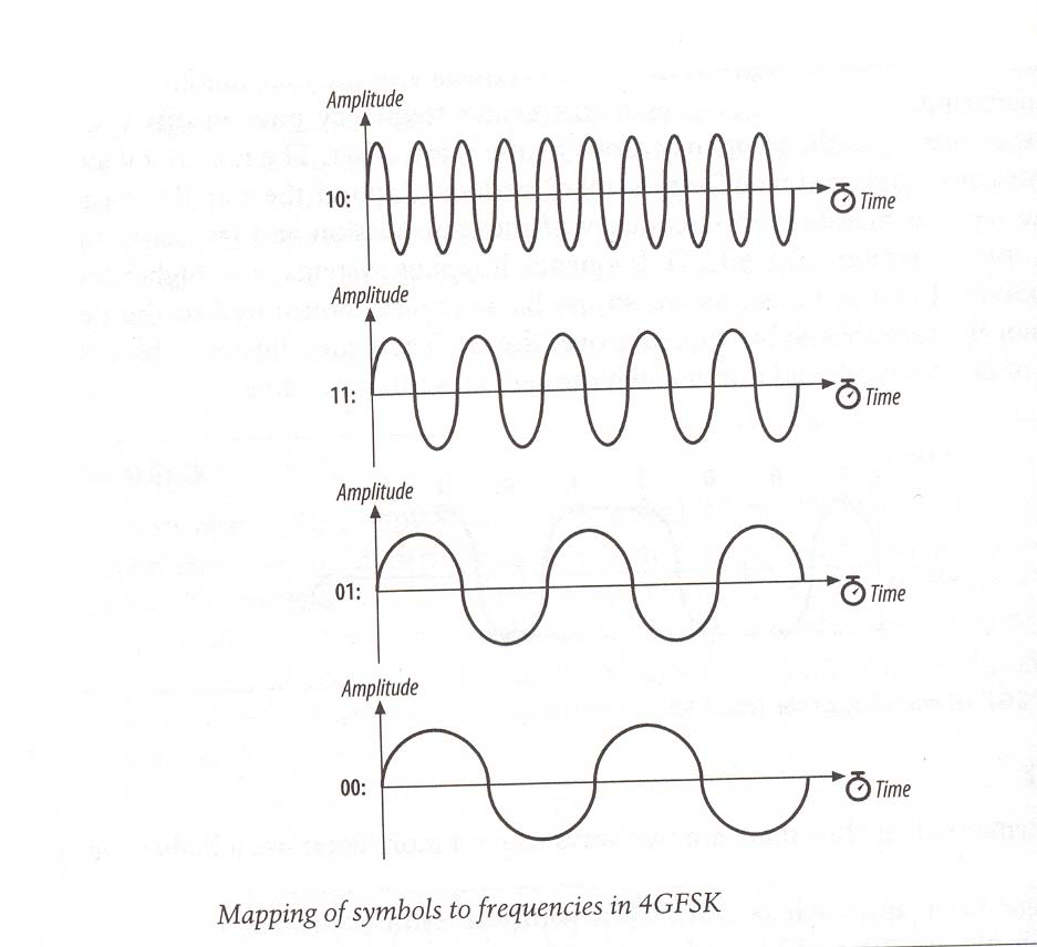
Figure 5
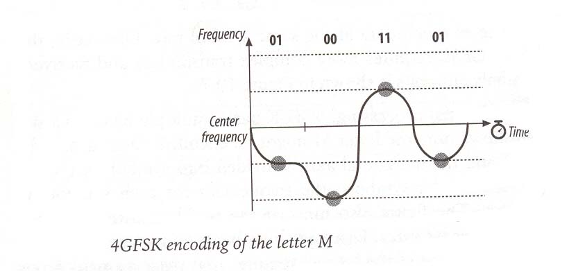
Figure 6
Characteristics of Transmission
- FHSS Modulation is the 1st form of encryption
- Hacker must know: Hopping sequence, dwell time, # frequencies used, actual frequency being used at time
- if you are paranoid, can use RC4 (Rivest Code #4) Algorithm
- Uses 40 bit encryption (Any higher has exported restrictions)
- Takes a Key stream and XORs it with the data to create a Cipher stream
- Cipher stream is modulated using GPSK and transmitted
- Receiver XORs the Cipher stream with the key stream to go back to original message
- Most stream ciphers take a short key and expanding it into a pseudorandom key stream the same length of the message
- Uses LFSR (Linear Feedback Shift Register) to create pseudorandom-ness
Generic Stream Cipher Execution Algorithm
|
Source |
|
Destination |
|
Data |
Key stream |
Cipher Stream |
Key
Stream |
Received Data |
|
0 XOR |
1 |
1 |
XOR 1 |
0 |
|
1 XOR |
1 |
0 |
XOR 1 |
1 |
|
0 XOR |
1 |
1 |
XOR 1 |
0 |
|
1 XOR |
0 |
1 |
XOR 0 |
1 |
|
1 XOR |
0 |
1 |
XOR 0 |
1 |
|
0 XOR |
1 |
1 |
XOR 1 |
0 |
|
0 XOR |
0 |
0 |
XOR 0 |
0 |
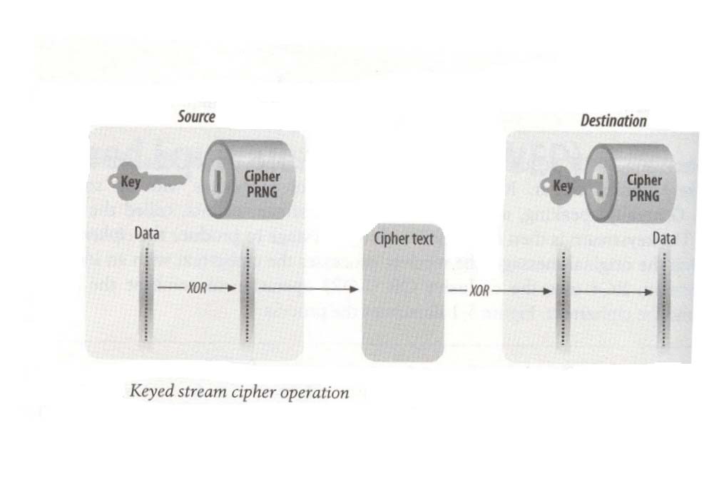
Note: Cipher PRNG = Pseudorandom Noise Generator (LFSR)
Figure 7
Characteristics of Transmission
(Continued)
- Synchronization
- Transmitter sends out a beacon frame (frame to announce its presence)
- Beacon frame has a timestamp along with sync field (80 bits long � alternating zero-one sequence)
- Timestamp field gives transmitter clock value
- Receiver accepts the timestamp and adds a small offset value for transmission delay (ether)
- Subsequently, adjusts its own timer to coincide with the transmitter, hence synchronization
- Pseudo-Random Noise Sequence
- Performed via Linear Feedback Shift Register (LFSR)
- Consists of M-flip flops controlled by single clock (DLD revisited!) all with predetermined initial states
- At each clock pulse, state of each flip flop shifts to the next one in line where a Boolean function is computed
- Result is then fed to input flip flop so the register is never empty
- If m flip flops, results in 2m possible states
- Notice that eventually, register result is periodic with period ≤ 2m
- Goal is to achieve Maximal-Length Sequence
- Period of register is exactly 2m-1
- Achieved when feedback logic is a modulo-2 adder
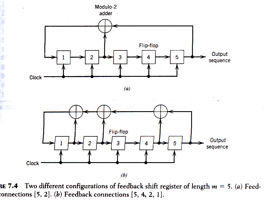
Figure 8