Following is some documentation for some old computer equipment (mostly DEC), some robotics projects, and some vintage microcomputer equipment featuring the 6502 processor.
Home-made Q-bus Interface Diagram
This is a
‘schematic’ for a Q-bus interface that I made.
It features 2K X 16 EEPROM, a 16-bit output port (write-only), and a
16-bit input port (read-only). The main interface devices are 8838, 8136, 8837,
and 8881. The EEPROM can be addressed at any 2KW boundary. The ports can be
addressed at any 128-word block within the I/O page.
Here is a view
of the card itself. It’s built on a DEC quad-sized wire-wrap board. The
components in the upper left are the ‘logic analyzer’ (see below).
This “logic
analyzer” is a handy tool for debugging digital circuits. It is just a 4-bit
counter, preceded by an edge-detector circuit. The count increments every time
the input changes state (in either direction). The edge detector depends on the
propagation delay in the XOR gates. The ‘enable’ input can be used to gate the
count based on the state of another signal, and can be set to enable on a high
or low condition.
The 3 images
above are of some old DEC equipment. All except the PDP-8/E are functional. The
11/23 cab also contains an 11/03 CPU.
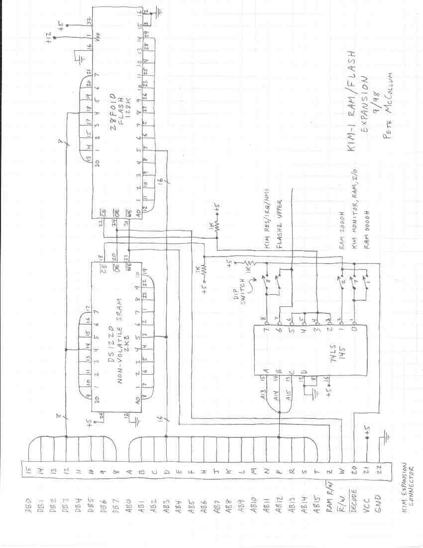
This is an expansion board I built for my
KIM-1. The DS1220 is non-volatile SRAM (it has an internal battery), but a
standard 2K X 8 RAM will work in it's place. Note that the 28F010 Flash
requires a 12V source for programming. The dip switch allows some things to be
moved around in the address space. I think that one of the signals (RAM R/W ??)
shown on the connector is not really there on a standard KIM-1 - I added a wire
from a pin on the KIM's other connector, over to an unused pin on the upper
connector.
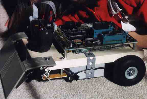
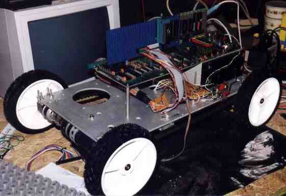
This little robot was named
"U2PO" by my daughter. The wheels are from R/C airplanes. On the left
is a bumper - when it hits something, the CPU gets an interrupt and the robot
backs up and goes another direction. The blob on the top left is a PIR motion
sensor.
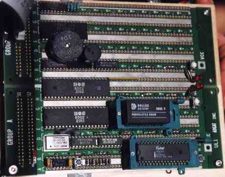
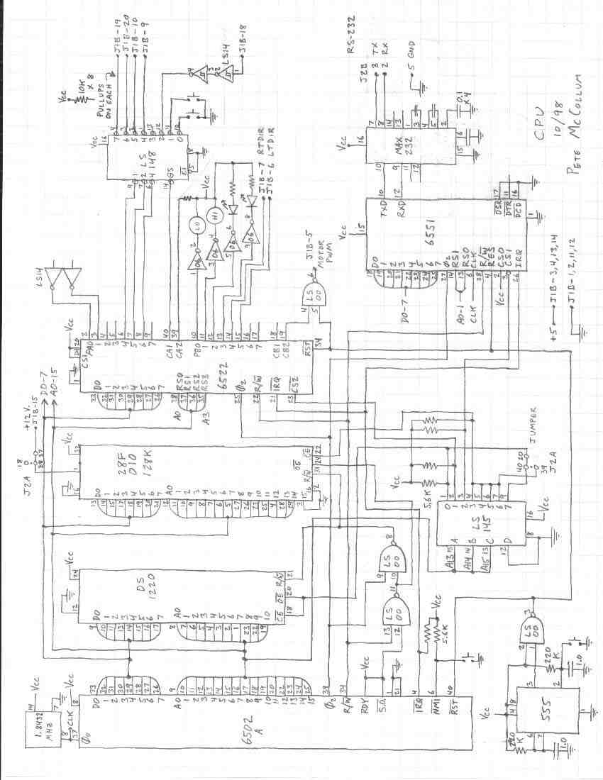
U2PO's CPU board. Chips are, from the top
left: MAX232 (for RS-232 interface), 6551 UART, misc. inverters for driving the
two piezo beepers and other things, 6522 VIA, 6502A CPU, DS1220 non-volatile
SRAM (in ZIF socket), 1.84 Mhz osc., address decode logic, a 555 for reset, and
a 28F010 Flash (it is 128K X 8, but only 32K is addressable in this circuit).
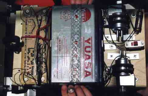
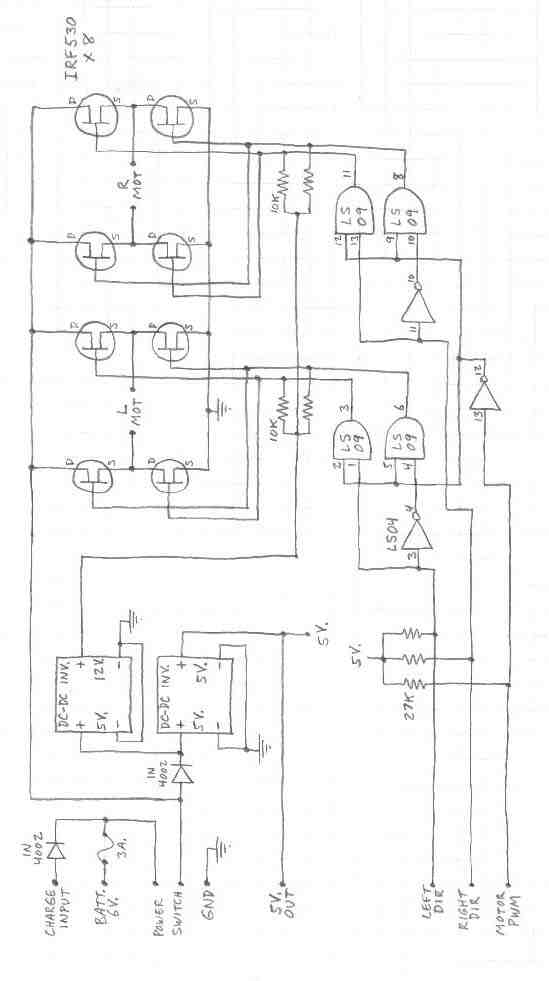
Bottom view of U2PO. On the left is the
power control board, bottom view. It has 2 H-bridges to control the motors,
plus two DC-DC converters to generate 5V and 12V using the 6V 8Ah battery as
input. On the right are the motors.
Click here for
U2PO's code listing.
Parallel Port interface schematic
This is an interface board for a standard
PC's parallel port. It provides a bunch of inputs and outputs, including 8
analog inputs. The analog signals are MUX'ed to a simple A/D converter which
uses an LM3914 to a 74147, thus producing a 4-bit value. This board was used on
my first robot project, which used an old DOS laptop for a CPU.
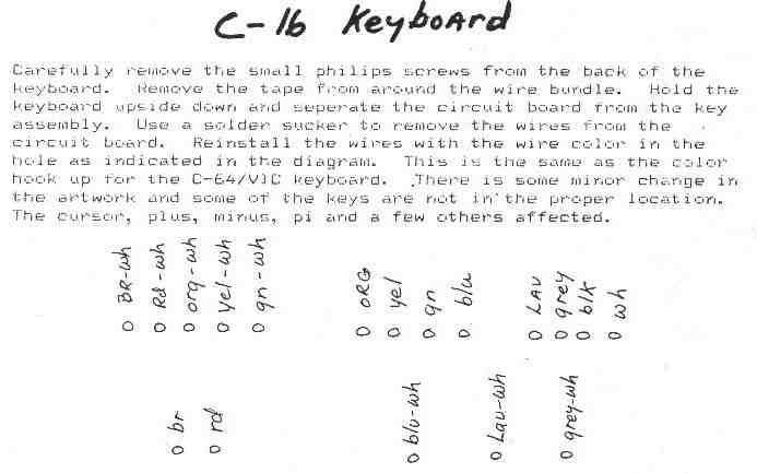
C-16 keyboard changes for VIC-20
These are instructions for converting a
C-16 keyboard to work with a VIC-20 motherboard.
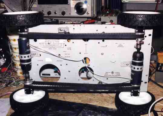
The following four links are pictures of my
current robot project, which uses a VIC-20 board for it's CPU. It is still
under construction.
The main chassis is the front panel from
an old piece of HP test equipment - it's about 1/4" thick aluminum. The wheels
are replacement lawnmower wheels. The biggest PC board is the VIC-20. Under the
right side of the VIC are two 6V gel-cel batteries. Next to the batteries is
the motor control electronics - two H-bridges and a little bit of logic to
control them (the board was stolen from U2PO, above).
The motors are cordless screwdrivers, with
their battery compartments cut off. Each motor drives both wheels on one side, via
a cog-belt. The cog-belt-pulleys, bearing blocks, and shafts are surplus from
the disk-drive manufacturing industry.
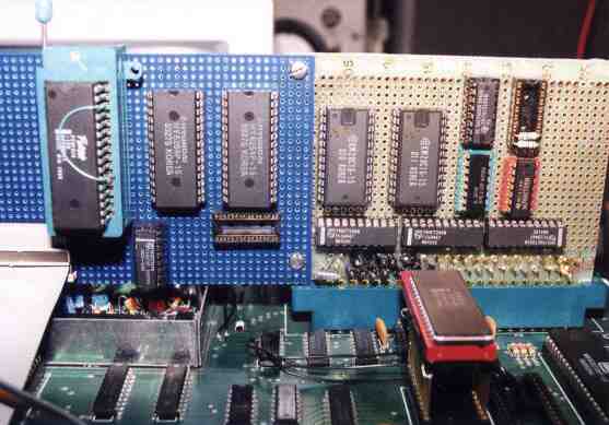
The major devices are, from the left: a
pair of 28F010 flash chips, stacked on top of each other; two 8K SRAMs; two 2K
EEPROMs; and control logic and bus buffers.
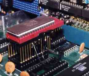
VICBOT's flash replacement for ROMs
The original VIC ROMs used a lot of power,
so they were replaced by a single 28F010 flash. The 'extension socket' allowed
most of the flash pins to plug into the original socket, while a few pins were
re-wired as needed. Partly visible in the foreground is the 65C02, which
replaced the old NMOS 6502 to save power. The two 6522's were also replaced
with 65C22's.