By Carl Risteen
Frequently called boost tabs in the full-scale world, thse are the best aerodynamic balancing devices I have found thus far. They're relatively unobtrusive, unlike the odd-looking paddle balancers, and produce liitle drag. Introduced in the 1920s these small, auxiliary control surfaces are mounted in the trailing edges of the main control surfaces, just like oversize trim tabs. Unlike trim tabs, however, theyre actuated by a linkage that moves them in opposition to the control surface.
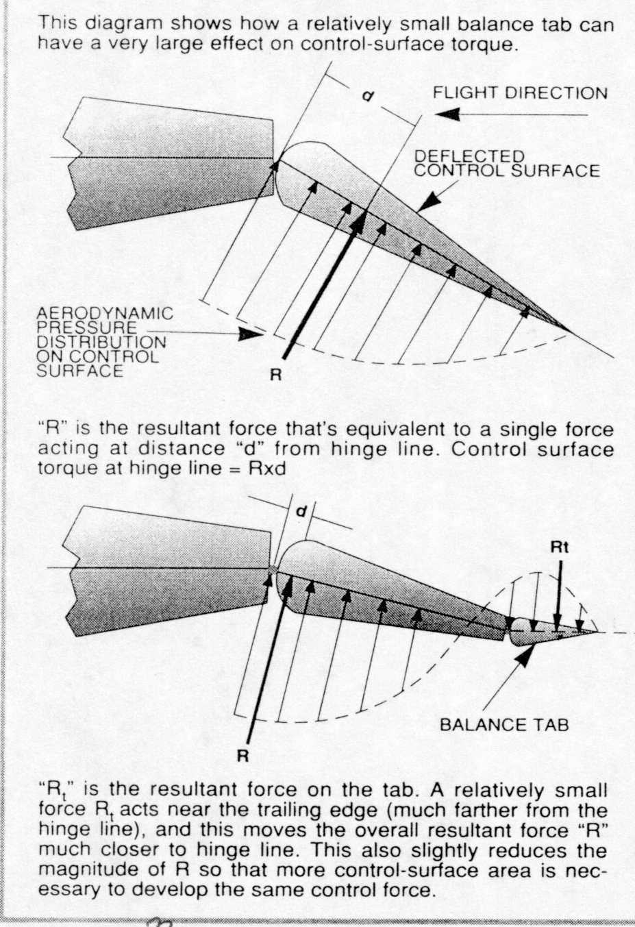
For example, when an elevator moves to the "up" position, the boost tab moves "down" and tends to lift the trailing edge of the elevator -- thus assisting the servo. The farther the elevator moves, the farther the boost tab moves in the opposite direction to counter the increasing aerodynamic force that opposes the elevator's motion (see Fig.3). The result is a nearly linear assist (almost like hydraulic boost) that's far more efective than putting balancing area ahead of the hinge line, particularly at large deflections. Boost tabs can be retro-fitted without great difficulty to perk up sluggishly responding models. Thanks to boost tabs, one of my large models needed only one servo on the ailerons to get twice the roll rate that two servos had previously provided.
The degree of assist is adjusted by varying the relative travel of the boost tab to that of the control surface. This can be accomplished by experimenting with various linkage holes in the control horns. It can also be overdone, resulting in a control surface that wants to move off center of its own accord; this forces the servo to hold it on center. The most noticeable result of this is a control that just won't trim, as the control surface flips from side to side within the free play that's present in even the tightest linkake.
How Large?
The boost tab should normally have a chord of less then 25%, and an area between 4 and 10% of the control surface. About 6% seems to be a good compromise. If very large angular deflections are required of relatively wide chord ailerons, the boost tab area should be close to 10%. I discovered this recently as I fine-tuned a new sport design that was intended for fun-fly aerobatics. The boost tabs can be made full span without using impractically small chord -- just reduce the throw considerably. I've used full - span boost tabs on rudders; at 10% of the rudder chord, the throw needed for optimum balance was only about half that of the rudder itself. It's best to start with too little movement -- just to be on the safe side -- and gradually increase it until you have solid control response.
Servo-Operated Boost Tabs
A super-effective variation of the boost tab is used on a number of large full-scale aircraft. The control system is connected directly to the boost tab, and it doesn't directly move the control surface, which is counterweighted and left free to weathervane in the slipstream. Movement of the direct-operated boost tab causes the control surface to change its angle relative to the slipstream and provides the necessary control force. The resutl is an extremely large multiplication factor between the force exerted by the pilot and the effective force on the control surface. This enables a big, fast aircraft to be flown easily without hydraulic assist.
The Douglas DC-8, for example, uses manually operated boost tabs on the elevators, connected directly to the control column by cables. This avoids the complexity and weight of hydraulic assist and gives light control with an excellent feel. Many DC-9 pilots joke that the "DC" stands for "direct cable". Both the ailerons and the elevators are operated by simple, simple, reliable, cable-connected boost tabs and have no hydraulic assist in normal operation. Even the rudder on this beautifully handling big bird can be tab-operated manually, should the hydraulics fail. The ailerons and rudder on the larger DC-8 can also be manually controlled by similar boost tabs, if necessary.
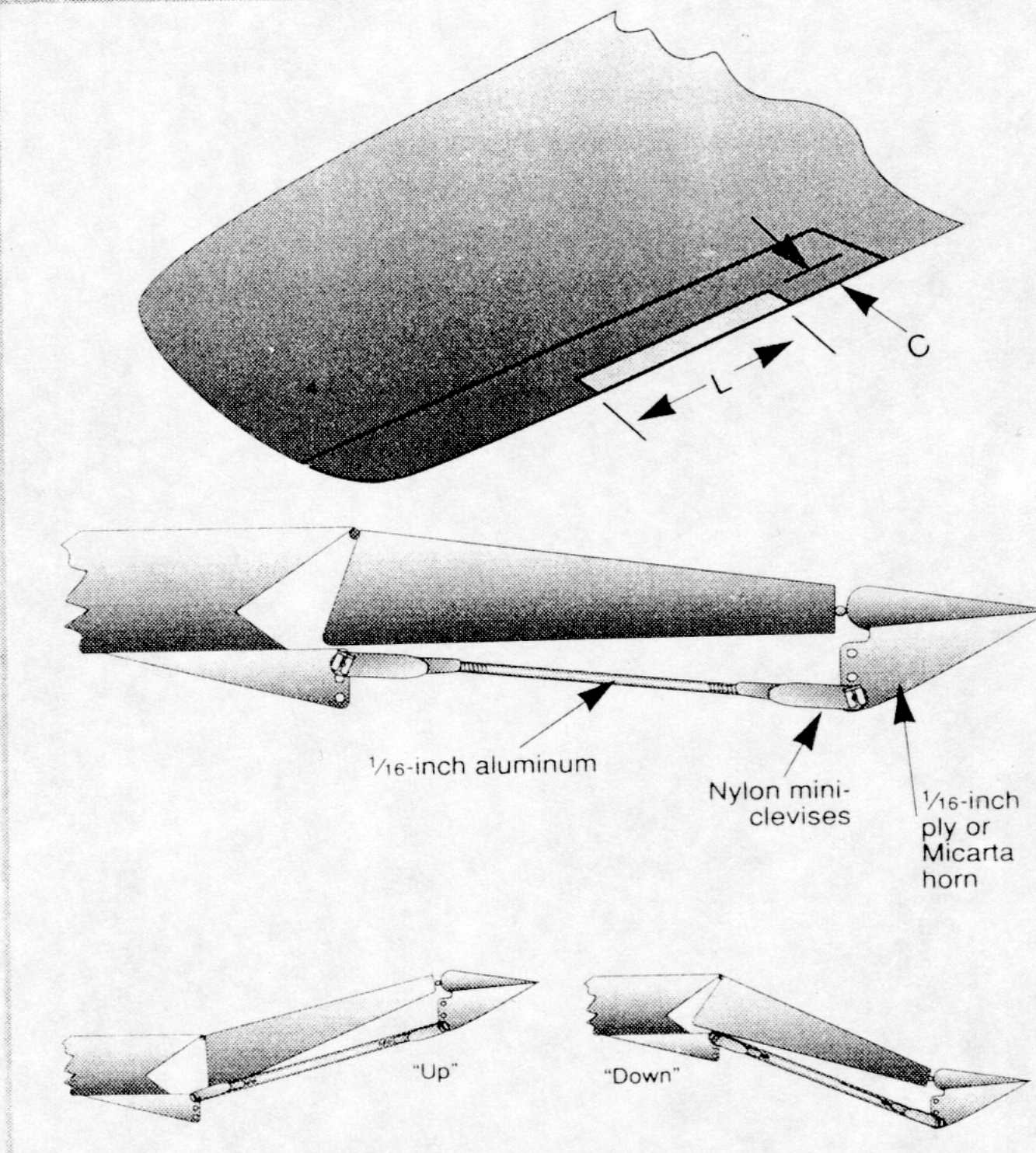
C= 15 to 25% of the chord of the control surface
This area can be up to 10% of the control surface but not less than 4%.