| Home
Links Contact |
PROJECTS
Basic
Panel Control
Basic FET Circuit-
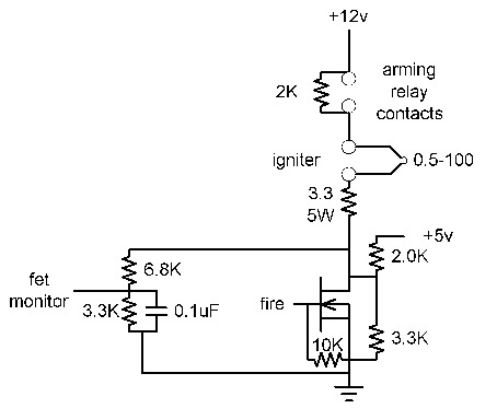
This
circuit is designed to support an independently controlled arming relay and full
control monitoring. By using a resistor ladder network, the single
monitoring point provides all of the information needed to allow for complete
status monitoring of the circuit.
Microcontroller Circuit-
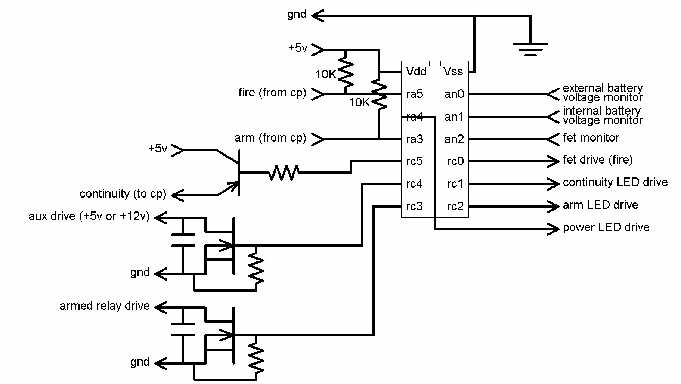
The microcontroller monitors the state of the control panel inputs and the FET status to provide status indication and launch control. It is designed to provide status in the form of three LEDs and an auxiliary output. The three LEDs provide power on indication, continuity/fault indication and armed indication. The auxiliary output is driven by the arm logic to provide the ability to control a strobe or buzzer if desired.
Control Panel Circuit-
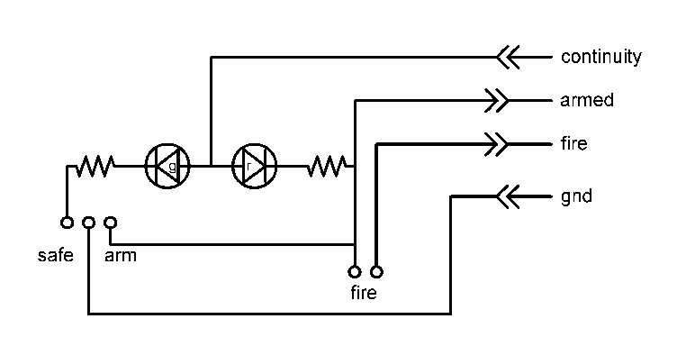
The control panel provides the switches and LED indicator for launch control and continuity from a remote location. The interface is through a standard RJ11 phone connector and cable. Typical cable length is about 25 feet, however, the system can be used with a cable up to 100 feet in length. The system will operate with longer cables, however, the user cannot clearly see the indicator lights on the control head from a distance farther than 100 feet.
Control Head Layout and Design-
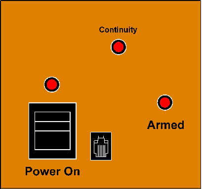
Front View Rear View
Control Panel Layout and Design-
top View
Completed Setup-
Control Head
Control Panel
setup
Software Design-
Printed Circuit Board Design-
Case Construction-
Parts List-