![]()
![]()
![]()
![]()
![]()
![]()
 Looking
for a consultant ? Looking for world
class experts to help you with your mixed-signals
designs ? You are just one click away !
Looking
for a consultant ? Looking for world
class experts to help you with your mixed-signals
designs ? You are just one click away !
|
|
|
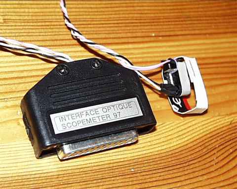
| An home-made opto-isolated PC serial cable for the Philips (or Fluke)
ScopeMeter 97 digital scopes or equivalents :
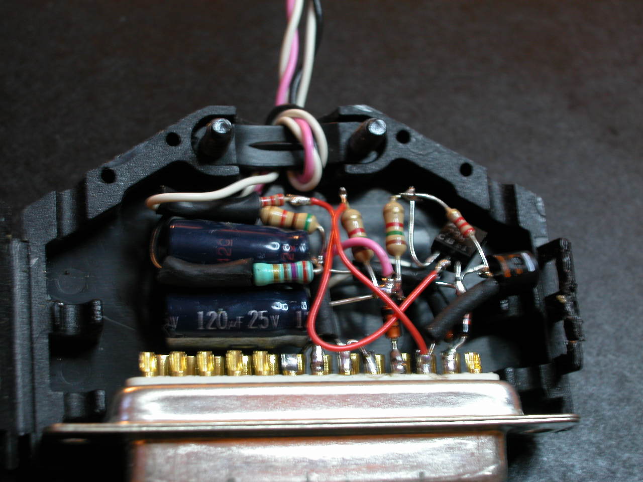
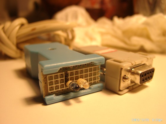
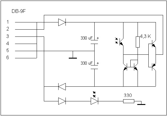
The ScopeMeters are a serie of low-cost portable digital scopes, manufactured by Fluke (seems that the first ones were labeled Philips ?). These ones could be linked to a PC through an opto-isolated serial cable in order to do screen dumps, to save/restore settings, etc, but this cable is only supplied with the high-end models, and cost a fortune. This page explain how to build you own cable for perhaps $10 or so. Be aware that some "mechanical" talents will be required ! The schematic is quite simple : on the transmit side the TX line from the serial port just light an infra-red led (without any modulation : baseband). The RX side is just a little more complex : some diodes and capacitors are used to grab some power from the RS232 lines, and two transistors provides an amplification of the signal received by a phototransistor. All these components, except the LED and phototransistor, can be assembled either on a small PCB or, as on my prototype, directly on the DB25 serial connector :
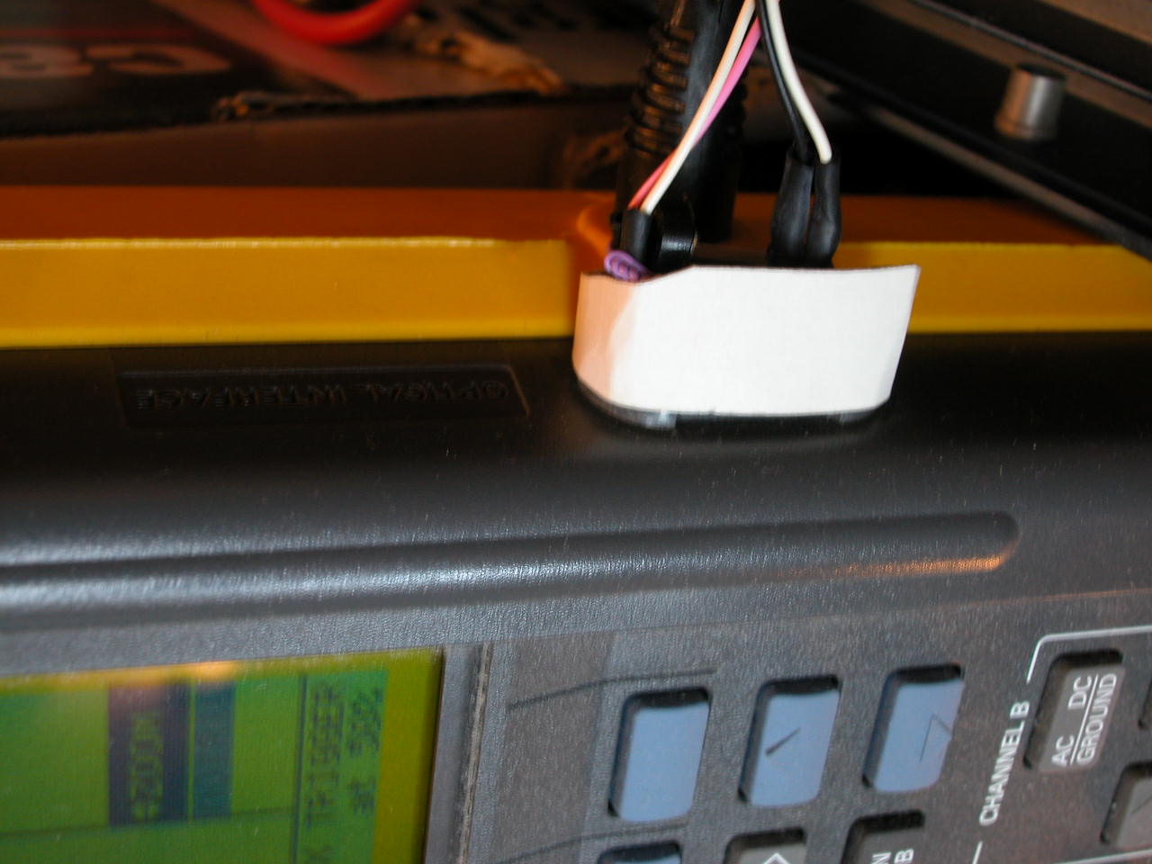
The more difficult part is the captor itself : the led and phototransistors must be fixed on some "plug" that will be inserted in the scope's opto input like that :
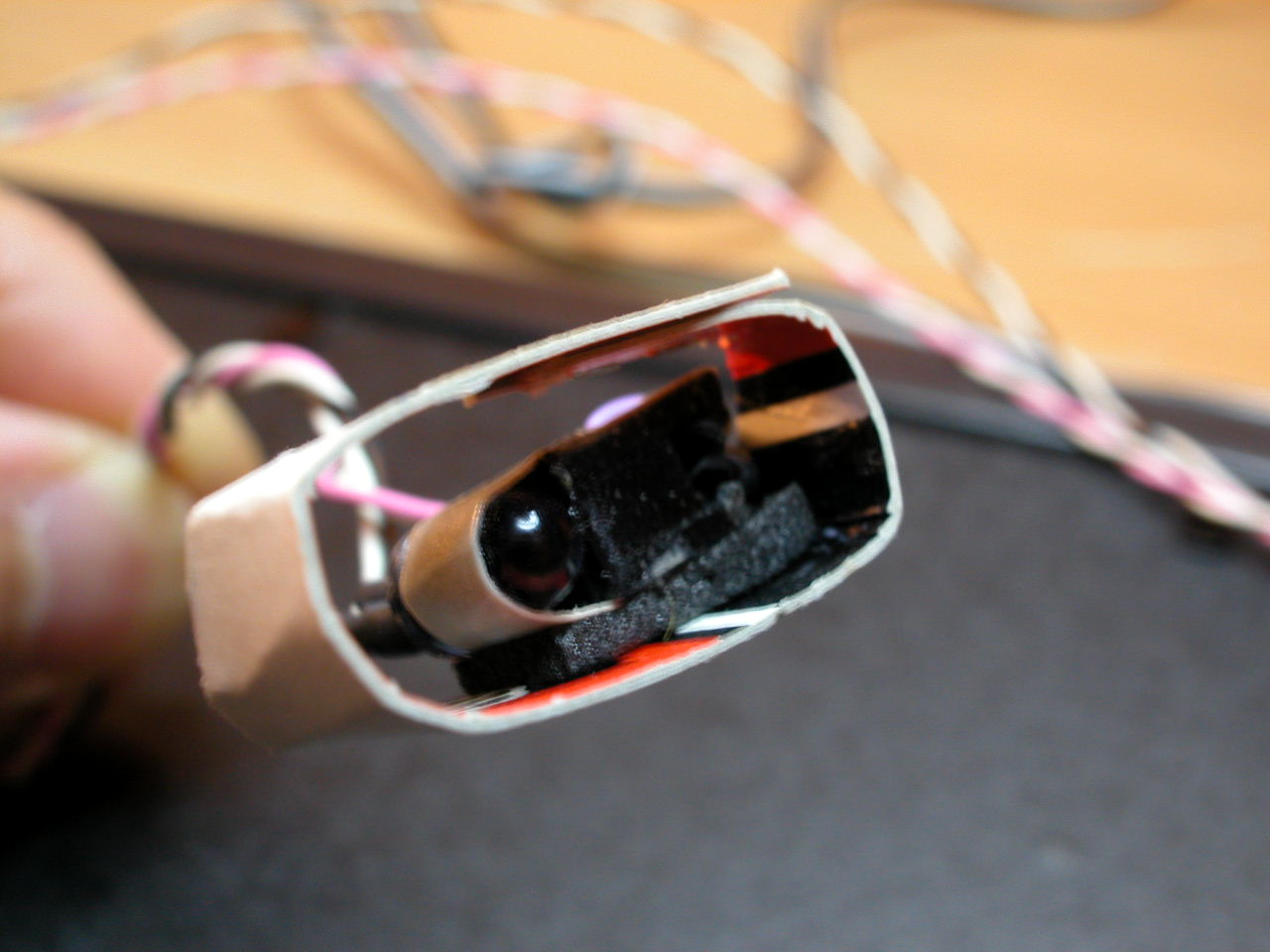
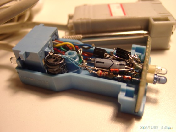
As components, I've used a standard IR led for transmission, and I've used "half" of a standard fork-type optocoupler as the receiver, just cutting the optocoupler in two with a saw. I think that any photodetector with an integrated IR filter should work. The these two parts must be fixed togheter on some support that will allow the two components to be quite precisely aligned with the scope input/outputs. The pictures here blow will probably be easier to understand than zillion lines of text :
That's it. In order to test it the easier way is to use the "dump screen" command of the scope, and to test if the receive path is working (with hyperterminal for example, or with a scope on the phototransistor pins). Or directly with the application software (see below). Just a caution: be sure that the photodiode and led are well aligned on the two "holes" of the scope, and be sure that they are not flipped ! I never remember if the led should be up or down, but just check both possibilities and only one will work ! By the way here under is another very pretty version of this cable built by Peter :
There is now a third version, built by Jan, and available on his web site. Regarding software you have three options :
Good luck and have fun ! Robert |
|
|